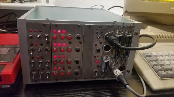
Homebrew mini metal PDP-8 (1976) Intersil 6100 code

I still haven’t found the start address on my Festo device. I now found this interesting German 1976 project of a former school master. He now using a Pi with it.

Dr. Kokavecz
More info and more photos (details of the PCBs) on this PDF (mainly in German)
http://www.s483465280.initial-website.co.uk/vintage/DOKUMENTATION_1.pdf

Programs including a BASIC-A for 6100 were on cassettes and aren’t shared and are mainly lost. At least there are some info, a handwritten BIN and RIM loader and the BASIC manual.

At 7777 is not a reset vector but the reset start address. That should be usually an index jump to 7776 (instruction 5776) and there is usually the start vector (like 0200).

In my code it’s different. The last 2 words look like index pointers. So it’s unclear if 7777 is data or code. Maybe CRC. Code does not make much sense (storing an empty AC somewhere then continue at 0).

L7762,
	TAD   C0035				/ 					  @@7762=1035
	AND   D0103				/ 					  @@7763=0103
	TAD   C7770				/ 					  @@7764=1370  
C7765,	7640				/ SZA CLA								
	JMP   L7755				/ 					  @@7766=5355
	JMP I C7756				/ long jump to L3406  @@7767=5756
C7770,	7772				/ SPA SNA SZL CLA HLT					       
C7771,	0070				/ AND   D0070							
D7772,	1104				/ TAD   D0104							
	SNA CLA					/ 					  @@7773=7650
	JMP I C7776				/ long jump to L3456  @@7774=5776   
D7775,	5777				/ JMP I C7777							
C7776,
C7776,	3456				/ DCA I D0056							  
	DCA I C7651				/ 	  				  @@7777=3651

Also of interest different ASCII values for input and output.
“/” is 57 or 257. He says 47 for input and 175 for output.
Also unclear are the 6xxx hardware IOTs that can be user defined.
He used 6031 etc instead of 6041 for keyboard (TTY?). Like other instructions multiple commands can be added into one instruction. I just have 6033. So just the input and missing TTY output.

He used assembler PALBART but maybe he just used compatible staight 8 code and not special Intersil code.
But all is interesting. As there’s are few 6100 code around. And 6120 is different (some other instructions, the SBC mainly using OS/8 and a disk image). I’m quite sure having found some short code for printing. But longer code sections, error handling etc are still missing.

2 Likes

That code at 7772 appears to make a decision to either JMP I through 7776 or 7777, ending up at either 3456 or 3651. Depending on the content of location 0104.

Yes, when coming from inside the code and if 7772 is code. (It would make sense as after start or reset AC is 0 and the start would be 3651 (at 7777). I’ve checked both code at 3651 and 3456.

But I can’t see that 7772 is code and I think it’s never called. 7772 is (by coincidence ?) data at 7770. But that is added with another value. Here’s a run with the default values.


[7762] IRQ,DLY,IE=0,1,0 L/AC:0/0000 MQ:0000 IR:1035 TAD 0035   ;Add operand to AC, ZP 0035
[7763] IRQ,DLY,IE=0,1,0 L/AC:0/1410 MQ:0000 IR:0103 AND 0103   ;AND operand with AC, ZP 0103
[7764] IRQ,DLY,IE=0,1,0 L/AC:0/1000 MQ:0000 IR:1370 TAD @@70   ;Add operand to AC, Current page @@70
[7765] IRQ,DLY,IE=0,1,0 L/AC:1/0772 MQ:0000 IR:7640 SZA CLA    ;Skip on AC = 0, Clear AC
[7766] IRQ,DLY,IE=0,1,0 L/AC:1/0000 MQ:0000 IR:5355 JMP @@55   ;Jump Current page @@55
[7755] IRQ,DLY,IE=0,0,0 L/AC:1/0000 MQ:0000 IR:4017 JMS 0017   ;Jump to subroutine ZP 0017
[0020] IRQ,DLY,IE=0,0,0 L/AC:1/0000 MQ:0000 IR:1126 TAD 0126   ;Add operand to AC, ZP 0126

2 pass PALBART is a bit different than d8tape and doesn’t detect 7772 as data but both last words as pointers

 4150 07762  1035  L07762, TAD D00035
 4151 07763  0103          AND D00103
 4152 07764  1370          TAD D07770
 4153 07765  7640  P07765, D07640
 4154 07766  5355          JMP L07755
 4155 07767  5756          JMP I P07756
 4156 07770  7772  D07770, 7772
 4157 07771  0070  D07771, 0070
 4158 07772  1104          TAD D00104
 4159 07773  7650          SNA CLA 
 4160 07774  5776  L07774, JMP I P07776
 4161 07775  5777  D07775, 5777
 4162 07776  3456  P07776, L03456
 4163 07777  3651  P07777, L03651

Code at 3651 is strange as AC is 0 in any way and there’s a branch if AC<0

[3651] IRQ,DLY,IE=0,1,0 L/AC:0/0000 MQ:0000 IR:7700 SMA CLA    ;Skip on AC < 0, Clear AC
[3652] IRQ,DLY,IE=0,1,0 L/AC:0/0000 MQ:0000 IR:5324 JMP @@24   ;Jump Current page @@24
[3724] IRQ,DLY,IE=0,0,0 L/AC:0/0000 MQ:0000 IR:7301 CLL CLA IAC;Clear L, Set AC to 0001
[3725] IRQ,DLY,IE=0,0,0 L/AC:0/0001 MQ:0000 IR:3141 DCA 0141   ;Deposit AC to memory then clear AC, ZP 0141
[3726] IRQ,DLY,IE=0,0,0 L/AC:0/0000 MQ:0000 IR:1133 TAD 0133   ;Add operand to AC, ZP 0133
[3727] IRQ,DLY,IE=0,0,0 L/AC:0/6753 MQ:0000 IR:3142 DCA 0142   ;Deposit AC to memory then clear AC, ZP 0142
[3730] IRQ,DLY,IE=0,0,0 L/AC:0/0000 MQ:0000 IR:4017 JMS 0017   ;Jump to subroutine ZP 0017
[0020] IRQ,DLY,IE=0,0,0 L/AC:0/0000 MQ:0000 IR:1126 TAD 0126   ;Add operand to AC, ZP 0126

Here’s the start of the other vector with a random value AC<>0, interestingly jumping back to the last page

[3456] IRQ,DLY,IE=0,1,0 L/AC:0/7770 MQ:0000 IR:3125 DCA 0125   ;Deposit AC to memory then clear AC, ZP 0125
[3457] IRQ,DLY,IE=0,1,0 L/AC:0/0000 MQ:0000 IR:1125 TAD 0125   ;Add operand to AC, ZP 0125
[3460] IRQ,DLY,IE=0,1,0 L/AC:0/7770 MQ:0000 IR:7650 SNA CLA    ;Skip on AC <> 0, Clear AC
[3462] IRQ,DLY,IE=0,1,0 L/AC:0/0000 MQ:0000 IR:5634 JMP I @@34 ;Jump Indexed Current page @@34
[7761] IRQ,DLY,IE=0,0,0 L/AC:0/0000 MQ:0000 IR:3260 DCA @@60   ;Deposit AC to memory then clear AC, Current page @@60
[7762] IRQ,DLY,IE=0,0,0 L/AC:0/0000 MQ:0000 IR:1035 TAD 0035   ;Add operand to AC, ZP 0035
[7763] IRQ,DLY,IE=0,0,0 L/AC:0/1410 MQ:0000 IR:0103 AND 0103   ;AND operand with AC, ZP 0103
[7764] IRQ,DLY,IE=0,0,0 L/AC:0/1000 MQ:0000 IR:1370 TAD @@70   ;Add operand to AC, Current page @@70
[7765] IRQ,DLY,IE=0,0,0 L/AC:1/0772 MQ:0000 IR:7640 SZA CLA    ;Skip on AC = 0, Clear AC
[7766] IRQ,DLY,IE=0,0,0 L/AC:1/0000 MQ:0000 IR:5355 JMP @@55   ;Jump Current page @@55
[7755] IRQ,DLY,IE=0,0,0 L/AC:1/0000 MQ:0000 IR:4017 JMS 0017   ;Jump to subroutine ZP 0017
[0020] IRQ,DLY,IE=0,0,0 L/AC:1/0000 MQ:0000 IR:1126 TAD 0126   ;Add operand to AC, ZP 0126

Maybe neither at 3456, 3651 nor 7762 is code but data. The main question is still the start address. But all continue at 20.

I am confused, as the code you are tracing isn’t the code I was commenting on. The code I commented on, I guess, is the PALBART code.

A JMS 17 would indeed pick up execution at 0020.

There doesn’t seem to be enough information for me to see much of either the PALBART code or the code you are executing.

1 Like

The first code is from d8tape, I later posted the same from PALBART.
I don’t know what information you need.
Here’s a trace run starting from 7772 but as said 7772 seems not to be called from anywhere. (Yes it’s jumping to that index and continues as shown and expected)

[7772] IRQ,DLY,IE=0,1,0 L/AC:0/0000 MQ:0000 IR:1104 TAD 0104   ;Add operand to AC, ZP 0104
[7773] IRQ,DLY,IE=0,1,0 L/AC:0/7006 MQ:0000 IR:7650 SNA CLA    ;Skip on AC <> 0, Clear AC
[7775] IRQ,DLY,IE=0,1,0 L/AC:0/0000 MQ:0000 IR:5777 JMP I @@77 ;Jump Indexed Current page @@77
[3651] IRQ,DLY,IE=0,0,0 L/AC:0/0000 MQ:0000 IR:7700 SMA CLA    ;Skip on AC < 0, Clear AC

Another issue is that there’s a subroutine to 20 but nowhere any returns. I mentioned elsewhere all the different ways of subroutines. But none seems to be the case here. Intersil has some different behavior/bugs. And there’s no 6100 emulator. Almost everything seems to be indexed and/or calculated. And parts of the Zeropage (ROM) is overwritten.

I found some (differently encoded) tables but I haven’t found out yet how they are read by the code. I posted lots of info (search for Festo, if you have much time). Or just ask. Thanks for your help!

I’m trying to gradually come up to speed with what you are doing, and what is done already. At first I thought the code snippets were from the Kokavecz machine, but now I think they are from your Festo project?

I tried again to follow the Festo thread. If I understand that correctly, there was a set of ROMs, with 6 bits of each byte used, presumably in pairs to make 12 bit words. It would be awesome if there was a .zip or similar somewhere with the ROM contents.

In the meantime, I’d look for sequences like these:
6031/6041 /skip if ready
JMP .-1 /wait for ready
6036/6046 /transfer a byte
Here 03 and 04 are the most common device codes for terminal I/O. These are the most common code sequences, in the sense that virtually all programs have them.

What I’d do in particular, is to dump the ROMs in octal. Ignoring the leading zero then, each byte displays half a word neatly. Revisiting the above, the sequences look like:
60
52 or 53
60
for the high byte. For the low byte:
31/41
.-1 /low b bits of previous address
36/46
These sequences should be relatively easy to search for in your octal ROM dumps.

Now, if the sequences for high and low appear at the same ROM offset, that is fairly strong evidence that those two ROMs form a pair, and which is high and which is low.

Your other thread seems to imply you believe you’ve got that sorted out by other means.

Vince

1 Like

Oh it’s you Vince. You have a great site!

Yes it’s from my Festo project. There are 8 ROMs and there are 2 possible combinations.
Pairs 7-3 8-4 5-1 6-2 as shown or less likely halfs swapped as 51627384.
I don’t have any 6031/6041 or 6036/6046 instructions. (I do have 6033 but no JMP or transfer.)
Maybe in my case 6407/6411/6415.

I’ve sent you a link to the ROM. (Empty page filled with NOPs, header and footer added) Thanks very much for your time!

A brief summary of the tables I found:
742-777: functional units and allowed device’s operations, latter ones in the first half word
1000-1777: table for these units? Eg. unit display at 1546, display location AP1 at 1627, AP4 at 1672.
6000-6177: special dedicated Sixbit for devices mnemonics. 02=A, 04=B. starting with NSB
144-177: units part 2 >77 (BCD encoded): 100 756 2132. 100= unit, 756= end of unit 1-7-7. 2132 maybe 32= 2 more keys allowed.

TTY inputs: U (maybe not for my device)
TTY outputs: /D 00000 - 00007 S: 0000270003 (Start-end, S=CRC) followed by addr+instr. and CR/LF and then Xoff.
For a disassembly with mnemonics /L instead of /D.
“/” seems to be 0057 at 6542 followed by Xon. “D” (104) seems to be at 6613. 10 is added for ASCII L. Code at 6606.
Printout initiated by the main PLC would be /S.
LCD output is BCD encoded. 0-9 blank, F-E. (E0=360. 3xblank = 6314, 3x_ = 7356). Values only confirmed for an attached PLC. Usually there’s 100 added on my device.

Some registers are 16 bits. Some values can be entered decimal but will be converted to octal. The devices instructions have 6 digits. A bit, a byte and a word (described elsewhere). There’s a syntax check which can be turned off.

Thanks! I haven’t associated your handle with a name yet – do we know each other?

I downloaded your ROM dump – thanks!

I confirmed on the photo that the data bits for 1-4 are separate from 5-8, and that Q7 and Q8 are not connected, at least on the solder side. That seems consistent with 6 bits of MSB/LSB in each group (1-4, 6-8) or ROMs. That only leaves a question about which ROM bit goes to each bit on the 6100. I’m inclined to suspect these are monotonically (in order) assigned, so the question is which is MSB.

I tried swapping the bits end-for-end, but the result wasn’t better. There were TTY IOT instructions in the result, but not in any pattern that made sense. So you probably have the bit order right.

I’m tempted to entertain the notion that 51627384 is the correct ordering, just because that would be monotonic. It would also save an inverter on one of the address bits, so it seems more likely.

The net effect of that would be to swap halves of your code. When I do that, the code at 0020 also seems more coherent.

Can you tell me anything about the I/O environment, perhaps from the manuals? I think I see an interrupt service routine, but I have no idea what it is doing yet. The code at 0001 still doesn’t make much sense to me, unless opcode 6075 is pushing the AC or something. That still leaves LINK unsaved, and an unsolved problem of how exactly execution gets over to the interrupt service routine.

I’ll keep looking and see if I find any recognizable code.

I have no idea what the paragraph that starts “TTY inputs: U” is talking about – something from the manual?

Vince

We don’t know each other. I know your site and tools.

I was quite sure that 7384… is the correct one. I did a lot of runs from different addresses and I often end up into the empty section what is there at 6000. That is reserved for later loading registers with ASCII and contains data, not code. The code, data in page 0 and the reset vectors looked more plausible to me. Most of the code has relative addressing anyway.

I/O: First there’s an EEPROM cartridge (with logic) on where the entered dedicated code is written to. One can import/export data from either TTY (V.24) or audio cassette (DIN). That is initiated by entering F-0/F-1) followed by some operands including baud settings like F10013. I can give more details about programming but I don’t have full schematics, IOTs or else. I haven’t found any of the other Intersil I/O ICs.

Then there are connectors to the PLC which can be remote controlled. There’s a steady busy signal exchanged, probably initiated by the PLC. I don’t have more info on that except the error code and timing. I also have a 9th ROM (few unknown non 12-bit data).

The TTY output is a sample for a printout. These (control) characters must be stored, like the printout style and also code for CRC calculation. The mnemonics are stored as special Sixbit. The ones here are the very few letters stored as ASCII.
TTY input was wrong. U and W are TTY outputs as well. One can input or change code via TTY but I think a TTY attached to the PLC.

The ROM must contain some more tables I haven’t found yet. Maybe major parts. Can you identify longer sections that aren’t code? Maybe 2200-2577 (ROM 7384). Or even a keyboard mapping?
One of the first things the device does must be a RAM check. Not sure about a ROM check.

Pleased to meet you, then :-).

I confess to still being puzzled about the correct ordering.

I have been studying the page at 5400 in your 7384 ordering. That page appears to me to be an interrupt service routine. It has two paths, a short one that doesn’t modify LINK, and another more complex path that needs to (and does) save and restore LINK. The longer path also seems to fetch and output character graphics, or some such thing. Hard to be sure without a description of the device involved, but it computes a pointer into auto-index register 16 and then outputs stuff pointed to in a loop (as if it were drawing characters).

Inside that part of the interrupt handler, there is some code starting at address 5460. This takes location 147, masks it, adds it to a table address from 5565, saves the result in 154, then branches to that place. I believe this is attempting to make use of the table of JMP instructions which can be found just following 5466. Essentially a “computed goto” depending on the state recorded in location 147.

The problem is, the base address of this table, as recorded in location 5565, is 7466, not 5466. Which would imply that this code only works correctly when loaded at 7400 instead of 5400. Either to code must get relocated, or we have the ordering not quite right.

Vince

1 Like

Also, moving 5400 to 7400 changes 7776 and 7777 to
0400 / Possible starting address
JMP I .-1 / Restart
which seems plausible.

1 Like

Thanks! Very interesting and strange.

The bit order and one of the 2 ROM combinations must be correct as I found text. Also the ROM stickers imply these pairs.
Relocation of 1 or more pages is possible and likely due to the empty page and as the RAM (768 words, 6 pages) is smaller than the ROM. But then there must be code or hardware for that. I don’t know the memory mapping. Bus and some registers could have 16 bits.

I’m not an expert, but starting from regular address 400 doesn’t make much sense to me. (Writing 1k words, after that TAD 0 and a NOP. Also much code inside page 0 which should rather be data, especially 147 and 154).
When moving everything up by 2000, 6000 with the text would be another memory field or moved as well. But what page is then at 400 and earlier? Or at the original 5400?

I tried swapping pages 5400-5577 to 7500-7777. Starting from 7400 there’s soon a HLT, a 6300 IOT and a NOP.

The device doesn’t have graphics. Just an LCD display. The table of 7 jump targets is interesting. They all load from 153 which is 7356. That is BCD encoded 777 and is either for outputting 3x_ on diplay location 4 but more likely here for 7 buttons (or 8 when not branching). I have 7 control mode keys and 8 instruction keys. Numpad 0-7 is also possible. Or 7 segments for the LCD.
Maybe a similar jump list at 3661 (ROM 7384, 4 targets for instructions OR+brackets ?)

At around 2513 seems to be values for the LCD. 4314 = 2xblank for 2 digits. There’s 3x777 and 4x 14 single blanks? And 4x7001. 6314 confirmed 3x blank. Also of interest 6 or 7 06xx values starting at 2505. Baud settings maybe at 4552.
/ and XON for printout at 6542.

I concur that at this point, the likely-hood that bit ordering is wrong is vanishingly small.

I found two more uses of the “computed goto” idiom. One is at 0420 in your 7384 dump, and suggests that the code currently ad 0xxx should be at 2xxx. The other is at 3651(as you mentioned) and suggests the code currently at 2xxx should be at 0xxx. If 4xxx should be 6xxx, then presumably 6xxx should be at 4xxx. That would imply a ROM ordering of 84736251.

I’d love to know more about the I/O environment, and the LCD in particular. Do you know which IOT control it and how? Even knowing that 4314 somehow encodes a pair of blanks is news, and helps explain what I suspect is a text unpacking routine. I still have no idea what you mean when you refer to baud settings or “/ and XON”.

Vince

Don’t forget about radix-50 text encoding, if all else fails.

8473… would result in having the empty page at page 0. I had excluded that then as I thought the start would be at 0.
Starting from 400 first seems plausible. But it overwrites everything with 3527 starting at 11. Maybe this is the RAM check? After that there are infinite loops. At 20 3527 acts then as instruction what is probably wrong. (But RAM <>ROM). Trace run below.

The LCD is the most interesting and complicated part. I’ve described it in 3 posts:

Help with c code (bit reversal) - #41 by mainframetom

Help reading EPROM (Intersil IM6654A) and analyze firmware - #64 by mainframetom

I don’t know the IOT. In the manual I have a table but I doubt that it’s stored as such. 2 characters forming one word, addition of 2 BCD values. Mainly for Ex and Fx. F0=0320. E0=360. 2 fixed values (bit patterns) for location 4 3x blank 6314 and 3x_ =7356. With that logic 4314 should be 2xblank. And 14 1x. 356 1x_

The LCD positions building 4 units/addresses AP1-AP4 0051-54 and can only be loaded. The allowed operation is stored at 762. There’s a command to delete all locations that is unit 0050. All this is only confirmed for the LCD of the PLC but it’s the same style. Loading itself is another instruction eg
…if…
then load AP4 040054 (4=load)
with decimal 8 070010 (7=with decimal, 10=octal)

I don’t know if there’s an LCD driver IC. I can’t remove that PCB without destroying it. The display can’t display text except F and E.
Text (mnemonics) stored at 6000 can only be printed out or exported. The text don’t have blanks. 00 as separator.

The baud settings are operands when exporting or importing. Eg import F 0 (r) (b) ADR, r=0 without reflection, 1 with reflection. b= 0 TTY 110 baud, 1=TTY 300 baud, 2=TTY 600 baud, 3=TTY 1200 baud, 4=Audio 110 baud… 7 Audio 1200 baud. Possible pattern found described here

PDP-8 mystery data, 8 values, LCD bit pattern?

/ and XON: A printout starting with /L 00000 - 00007 S: 0000270003. “/” is ASCII 2F what is 0057 octal. That is stored at 6542 followed by 21 what is control character XON (DC1). XOFF 23 is at 6570, CR+LF 15/12 could be at 572. The mnemonics printed after that aren’t stored as ASCII but as a unique Sixbit. You found a table here

Festo mnemonics text found in ROM code (new PDP-8 encoding)

[0400] IRQ,DLY,IE=0,1,0 L/AC:0/0000 MQ:0000 IR:6007 CAF        ;KK8-E: Clear all flags
[0401] IRQ,DLY,IE=0,1,0 L/AC:0/0000 MQ:0000 IR:1354 TAD @@54   ;Add operand to AC, Current page @@54
[0402] IRQ,DLY,IE=0,1,0 L/AC:0/6100 MQ:0000 IR:6415 SRS1       ;DP8-EAEB: Read Status 1
[0403] IRQ,DLY,IE=0,1,0 L/AC:0/6100 MQ:0000 IR:1273 TAD @@73   ;Add operand to AC, Current page @@73
[0404] IRQ,DLY,IE=0,1,0 L/AC:1/0402 MQ:0000 IR:6415 SRS1       ;DP8-EAEB: Read Status 1
[0405] IRQ,DLY,IE=0,1,0 L/AC:1/0402 MQ:0000 IR:1300 TAD @@00   ;Add operand to AC, Current page @@00
[0406] IRQ,DLY,IE=0,1,0 L/AC:1/1002 MQ:0000 IR:6414 SRS2       ;DP8-EAEB: Read Status 2
[0407] IRQ,DLY,IE=0,1,0 L/AC:1/1002 MQ:0000 IR:1272 TAD @@72   ;Add operand to AC, Current page @@72
[0410] IRQ,DLY,IE=0,1,0 L/AC:1/3527 MQ:0000 IR:7421 MQL        ;Load MQ from AC then clear AC
[0411] IRQ,DLY,IE=0,1,0 L/AC:1/0000 MQ:3527 IR:1270 TAD @@70   ;Add operand to AC, Current page @@70
[0412] IRQ,DLY,IE=0,1,0 L/AC:1/7411 MQ:3527 IR:3000 DCA 0000   ;Deposit AC to memory then clear AC, ZP 0000 
[0413] IRQ,DLY,IE=0,1,0 L/AC:1/0000 MQ:3527 IR:1313 TAD @@13   ;Add operand to AC, Current page @@13
[0414] IRQ,DLY,IE=0,1,0 L/AC:1/0010 MQ:3527 IR:3010 DCA 0010   ;Deposit AC to memory then clear AC, ZP 0010
[0415] IRQ,DLY,IE=0,1,0 L/AC:1/0000 MQ:3527 IR:7501 MQA        ;OR MQ with AC
[0416] IRQ,DLY,IE=0,1,0 L/AC:1/3527 MQ:3527 IR:3410 DCA I 0010 ;Deposit AC to memory then clear AC, Indexed ZP 0010 [Auto pre-inc]
[0417] IRQ,DLY,IE=0,1,0 L/AC:1/0000 MQ:3527 IR:2000 ISZ 0000   ;Increment operand and skip if zero, ZP 0000 
[0420] IRQ,DLY,IE=0,1,0 L/AC:1/0000 MQ:3527 IR:5215 JMP @@15   ;Jump Current page @@15
[0415] IRQ,DLY,IE=0,0,0 L/AC:1/0000 MQ:3527 IR:7501 MQA        ;OR MQ with AC

[0426] IRQ,DLY,IE=0,0,0 L/AC:1/3527 MQ:3527 IR:7041 CIA        ;2s Complement AC
[0427] IRQ,DLY,IE=0,0,0 L/AC:1/4251 MQ:3527 IR:1410 TAD I 0010 ;Add operand to AC, Indexed ZP 0010 [Auto pre-inc]
[0430] IRQ,DLY,IE=0,0,0 L/AC:0/0000 MQ:3527 IR:7640 SZA CLA    ;Skip on AC = 0, Clear AC
[0432] IRQ,DLY,IE=0,0,0 L/AC:0/0000 MQ:3527 IR:2000 ISZ 0000   ;Increment operand and skip if zero, ZP 0000 

[0431] IRQ,DLY,IE=0,0,0 L/AC:1/0000 MQ:3527 IR:5335 JMP @@35   ;Jump Current page @@35
[0535] IRQ,DLY,IE=0,0,0 L/AC:1/0000 MQ:3527 IR:1271 TAD @@71   ;Add operand to AC, Current page @@71
[0536] IRQ,DLY,IE=0,0,0 L/AC:1/0371 MQ:3527 IR:6410 SSRG       ;DP8-EAEB: Skip if Ring Flag
[0537] IRQ,DLY,IE=0,0,0 L/AC:1/0371 MQ:3527 IR:1010 TAD 0010   ;Add operand to AC, ZP 0010
[0540] IRQ,DLY,IE=0,0,0 L/AC:1/0407 MQ:3527 IR:6411 SSCA       ;DP8-EAEB: Skip if CarrierAGC Flag
[0541] IRQ,DLY,IE=0,0,0 L/AC:1/0407 MQ:3527 IR:5341 JMP @@41   ;Jump Current page @@41
[0541] IRQ,DLY,IE=0,0,0 L/AC:1/0407 MQ:3527 IR:5341 JMP @@41   ;Jump Current page @@41

[0542] IRQ,DLY,IE=0,0,0 L/AC:1/0407 MQ:3527 IR:7001 IAC;Increment AC
[0543] IRQ,DLY,IE=0,0,0 L/AC:1/0410 MQ:3527 IR:7001 IAC;Increment AC
[0544] IRQ,DLY,IE=0,0,0 L/AC:1/0411 MQ:3527 IR:7001 IAC;Increment AC
[0545] IRQ,DLY,IE=0,0,0 L/AC:1/0412 MQ:3527 IR:7001 IAC;Increment AC
[0546] IRQ,DLY,IE=0,0,0 L/AC:1/0413 MQ:3527 IR:3142 DCA 0142   ;Deposit AC to memory then clear AC, ZP 0142
[0547] IRQ,DLY,IE=0,0,0 L/AC:1/0000 MQ:3527 IR:1036 TAD 0036   ;Add operand to AC, ZP 0036
[0550] IRQ,DLY,IE=0,0,0 L/AC:1/3527 MQ:3527 IR:3141 DCA 0141   ;Deposit AC to memory then clear AC, ZP 0141
[0551] IRQ,DLY,IE=0,0,0 L/AC:1/0000 MQ:3527 IR:3151 DCA 0151   ;Deposit AC to memory then clear AC, ZP 0151
[0552] IRQ,DLY,IE=0,0,0 L/AC:1/0000 MQ:3527 IR:3076 DCA 0076   ;Deposit AC to memory then clear AC, ZP 0076
[0553] IRQ,DLY,IE=0,0,0 L/AC:1/0000 MQ:3527 IR:4017 JMS 0017   ;Jump to subroutine ZP 0017
[0020] IRQ,DLY,IE=0,0,0 L/AC:1/0000 MQ:3527 IR:3527 DCA I 0127 ;Deposit AC to memory then clear AC, Indexed ZP 0127
[0021] IRQ,DLY,IE=0,0,0 L/AC:1/0000 MQ:3527 IR:3527 DCA I 0127 ;Deposit AC to memory then clear AC, Indexed ZP 0127

Thanks, I’ll try to get up to speed.

I’m thinking that device at 641x isn’t doing our simulators much good. I want to figure out how to configure it out of my SIMH runs. From reading the source, I’d thought the test pattern was 2525, not 3527.

Anyway, I ran the simulation for a while, then interrupted it and had a look around. Here’s what ended up in page 0:
0000/1157 5427 7000 7000 7000 7000 7000 7000
0010/0534 0140 0000 0000 0000 0000 0000 0557
0020/1417 3131 5531 0400 1423 2023 5021 7400
0030/0602 0600 0601 0603 0604 0007 0010 0037
0040/4314 7777 7777 7777 0652 0600 0047 0047
0050/4314 7777 6314 4000 0014 0014 0014 0014
0060/0000 0000 0000 0000 0000 0000 0000 0000
0070/0000 0000 0000 0000 0000 0000 0000 0000
0100/0000 0000 0000 0000 0000 0000 0000 0000
0110/0000 0000 0000 0000 0000 0000 0000 0000
0120/0000 0000 0000 0000 0000 0000 0000 0000
0130/0000 0000 0000 0000 0000 0000 0000 0000
0140/0000 0010 0004 0000 0000 0000 0000 0000
0150/0000 0000 0000 0000 0000 0000 0000 0000
0160/0000 0000 0000 0000 0000 0000 0000 0000
0170/0000 0000 0000 0000 0000 0000 0000 0000

Vince

1 Like

This is interesting, as we finally get to see what “JMS 17” does.
Apparently it fetches the next word, then branches to the address contained there. A kind of “far JMP”:
JMS 17 /Far JMP
6100 /Destination address

The address in auto-index 17 is also very convenient for fetching arguments and even doing a ‘return’, converting the far JMP into far JMS. The value 0557 actually suggests that the JMS 17 at 0553 had gone to 6100, had fetched a couple of arguments there, and eventually returned to location 0557.

I tried ROM 8473 on different emulators. I think the 641x instructions aren’t a problem there.

I also found 2525. And it’s loaded correctly into MB. We have 1002 added, a sum of a device status read (2 bits). We can simply manually change that. Test pattern is written to pages 0+1.

There’s later a loop in 1152 writing data. After that a jump to 1 and to 7400 and 7436. Then 542, 20, 1123, 20, 1133, After IOF a loop at 1142 and 1152 and back to 1142.
I had to manually skip 2x to reach 1123 on pd8emu.

But at some point when there’s a branch to 20 (after 1164 or 553), that contains later the test pattern as well and that turns into an instruction. Maybe due to different 6100 behavior. Maybe it should be 17? Or 20 at current page instead of page 0. Or start at 400 is wrong.

The far jump sounds plausible. But at 6102 is a JMP I 23.

Data:
That data from 20-57 is a copy from 475 (2475 in ROM 7384). As said that looks like an LCD output. Probably the (default) LCD memory content. And having this on page 0 it’s maybe the temp storage. Or all possible LCD outputs. Or a mask for input or error output.

The line at 40 first looks like 3 digits and that would be the lower line and 4x14 with 4 digits the upper line. But the 3 digits (decimal) holding 4 values. And the upper line is octal. One of the 7777 could be the value. 6314 are 3 blks that must be the lower line.

I assume that 4000 is the little square that automatically appears as separator. The 06xx could be the special symbols. There’s a little dot in the upper line (displayed when power up) and 4 symbols at the left of the lower line. 2 symbols are for the remote-control mode each having 2 variants, the other 2 are * and ; for programming represent ELSE and FURTHERMORE which both is a “1”, the left digit from an instruction. Error code E (top left) can blink, same the remote-control symbols. On the MacOS emu 0652 is 8bit ASCII for “*” and 47 for “'” what is part of the remote-control symbols. But could be a coincidence.

I aligned it this way. I think data continues, even over the next page. A bit later again 0652. 060x could also be addresses for the display. Or maybe not LCD at all.

 0602 0600 0601 0603 
 0604 0007 0010 0037 4314 7777 7777 7777 
 0652 0600 0047 0047 4314 7777 6314 
 4000 0014 0014 0014 0014 1271              4x blank
 6410 1010                                  (still data?
 6411 5341 
  _   7001 7001 7001 7001     
 3142 1036
 3141 3151 3076 4017 
 6100 1123 
 0000 1133
 0652 0000 7053 7010 
 0400 0064 
 7767 1113
 1071 2371 7773 7760 3200 0000 0000 0000

At 0023 I see another “far call” code trampoline, implemented without auto-indexing. Perhaps this allows nested far calls, each with their own argument/return pointer.

1 Like

The code is very hard to check when running from another address with an empty page 0.
I think I’ll better populate page 0 (ROM) first with your memory output.
I will check some other emulators supporting different PDP-8 models. (Aconit, Wineight). I haven’t checked that on SIMH yet.

I still haven’t found any code reading my tables but maybe I just have.
Finding code for the text table should be the easiest as there’s known the most. Maybe the pointer isn’t 4000 but 4001 or 3777 or at the end of value 1 or end of the table. The mnemonics are sorted by unit numbers and these are in table 1 and 4. The printout control characters and code are around 4541. I think a far jump to 2700 (just above table 1). Near that an AND 77 for extracting the unit and interesting 65xx IOTs.

Most tables are now together.
Table 1 at 2742-2777
Table 2 at 3000-4000
Table 3 at 4000-4200
(Table 4) at 2144.

I only found these 2 interesting code segments both with 2 IOTs writing 2 words. (TTY input or less likely keyboard?). The future operands from page 0 are unknown. JMS I 30 will be to 602. There’s a JMP I 33 what is to 603 at there’s a JMP I 34 what is 604 and there’s a JMP I 45 what is 600. There’s a JMP I 32 what is 601 there’s again JMP I 30. Not sure if this is plausible. 45 is in the middle of my assumed LCD default values.

[7605] IRQ,DLY,IE=0,1,0 L/AC:0/0000 MQ:0000 IR:6417 SRCD       ;DP8-EAEB: Read Character Detected
[7606] IRQ,DLY,IE=0,1,0 L/AC:0/0000 MQ:0000 IR:6407 SRTA       ;DP8-EAEB: Read Transfer Address Register
[7607] IRQ,DLY,IE=0,1,0 L/AC:0/0000 MQ:0000 IR:7450 SNA        ;Skip on AC <> 0
[7610] IRQ,DLY,IE=0,1,0 L/AC:0/0000 MQ:0000 IR:5302 JMP @@02   ;Jump Current page @@02
[7702] IRQ,DLY,IE=0,0,0 L/AC:0/0000 MQ:0000 IR:1164 TAD 0164   ;Add operand to AC, ZP 0164
[7703] IRQ,DLY,IE=0,0,0 L/AC:0/7000 MQ:0000 IR:0035 AND 0035   ;AND operand with AC, ZP 0035
[7704] IRQ,DLY,IE=0,0,0 L/AC:0/7000 MQ:0000 IR:3164 DCA 0164   ;Deposit AC to memory then clear AC, ZP 0164
[7705] IRQ,DLY,IE=0,0,0 L/AC:0/0000 MQ:0000 IR:3163 DCA 0163   ;Deposit AC to memory then clear AC, ZP 0163
[7706] IRQ,DLY,IE=0,0,0 L/AC:0/0000 MQ:0000 IR:5301 JMP @@01   ;Jump Current page @@01
[7701] IRQ,DLY,IE=0,0,0 L/AC:0/0000 MQ:0000 IR:5430 JMP I 0030 ;Jump Indexed ZP 0030
[7000] IRQ,DLY,IE=0,0,0 L/AC:0/0000 MQ:0000 IR:5123 JMP 0123   ;Jump ZP 0123
[0123] IRQ,DLY,IE=0,0,0 L/AC:0/0000 MQ:0000 IR:7000 No operation;

[7625] IRQ,DLY,IE=0,0,0 L/AC:0/0000 MQ:0000 IR:6417 SRCD       ;DP8-EAEB: Read Character Detected
[7626] IRQ,DLY,IE=0,0,0 L/AC:0/0000 MQ:0000 IR:6407 SRTA       ;DP8-EAEB: Read Transfer Address Register
[7627] IRQ,DLY,IE=0,0,0 L/AC:0/0000 MQ:0000 IR:7650 SNA CLA    ;Skip on AC <> 0, Clear AC
[7630] IRQ,DLY,IE=0,0,0 L/AC:0/0000 MQ:0000 IR:5236 JMP @@36   ;Jump Current page @@36
[7636] IRQ,DLY,IE=0,0,0 L/AC:0/0000 MQ:0000 IR:1136 TAD 0136   ;Add operand to AC, ZP 0136
[7637] IRQ,DLY,IE=0,0,0 L/AC:0/7000 MQ:0000 IR:1136 TAD 0136   ;Add operand to AC, ZP 0136
[7640] IRQ,DLY,IE=0,0,0 L/AC:1/6000 MQ:0000 IR:3136 DCA 0136   ;Deposit AC to memory then clear AC, ZP 0136
[7641] IRQ,DLY,IE=0,0,0 L/AC:1/0000 MQ:0000 IR:2135 ISZ 0135   ;Increment operand and skip if zero, ZP 0135
[7642] IRQ,DLY,IE=0,0,0 L/AC:1/0000 MQ:0000 IR:5224 JMP @@24   ;Jump Current page @@24
[7624] IRQ,DLY,IE=0,0,0 L/AC:1/0000 MQ:0000 IR:1136 TAD 0136   ;Add operand to AC, ZP 0136
[7625] IRQ,DLY,IE=0,0,0 L/AC:1/6000 MQ:0000 IR:6417 SRCD       ;DP8-EAEB: Read Character Detected
[7626] IRQ,DLY,IE=0,0,0 L/AC:1/6000 MQ:0000 IR:6407 SRTA       ;DP8-EAEB: Read Transfer Address Register
[7627] IRQ,DLY,IE=0,0,0 L/AC:1/6000 MQ:0000 IR:7650 SNA CLA    ;Skip on AC <> 0, Clear AC
[7631] IRQ,DLY,IE=0,0,0 L/AC:1/0000 MQ:0000 IR:1131 TAD 0131   ;Add operand to AC, ZP 0131
[7632] IRQ,DLY,IE=0,0,0 L/AC:1/7000 MQ:0000 IR:7640 SZA CLA    ;Skip on AC = 0, Clear AC
[7633] IRQ,DLY,IE=0,0,0 L/AC:1/0000 MQ:0000 IR:5302 JMP @@02   ;Jump Current page @@02
[7702] IRQ,DLY,IE=0,0,0 L/AC:1/0000 MQ:0000 IR:1164 TAD 0164   ;Add operand to AC, ZP 0164
[7703] IRQ,DLY,IE=0,0,0 L/AC:1/7000 MQ:0000 IR:0035 AND 0035   ;AND operand with AC, ZP 0035
[7704] IRQ,DLY,IE=0,0,0 L/AC:1/7000 MQ:0000 IR:3164 DCA 0164   ;Deposit AC to memory then clear AC, ZP 0164
[7705] IRQ,DLY,IE=0,0,0 L/AC:1/0000 MQ:0000 IR:3163 DCA 0163   ;Deposit AC to memory then clear AC, ZP 0163