Computers / computer people on coins and stamps - Zuse undeciphered code

I recently found this German 2010 10 EUR coin showing Konrad Zuse (100th anniversary). This one is partially gold plated. Usual coins are just silver


On top is a 4-track paper tape, I recently had a post about 4 tracks
PDP-8 stats program, Ferranti Sirius emulator, papertapes with 4 rows only
Can someone decode that or the bits below. But I assume it’s just random garbage.
There was also a stamp
zusestamp

On commons is a category
Category:Computers on stamps - Wikimedia Commons
but I haven’t found coins, just
Category:Scientists on coins - Wikimedia Commons

There are many modern coins like krypto currency coins and the like, but who knows others?

1 Like

Well. In all honesty, I first googled it. If someone else had found it, no point in investing effort. However, I couldn’t find anything relevant.

So, the first thing I noticed (after typing all the bits in a notepad) is that the total number of “bits” is 182, which is not divisible by 8, so, if this contains data, it’s not ending at the whole byte marker.

Second, assuming there could be ascii, first character would be ‘n’, second is ‘]’, so unless someone is attempting emojis on a coin, that’s not it either.

Lastly (and I stopped here), I made a long string of all bits and used a trick to observe any patterns in the data.

coin bits

Didn’t see anything, so I’d say it ‘may’ be just random data.

However, for whoever wants to have more fun with it, here’s the string:

01101110010111011110001001001010010010110011010110111001011101010010011010100101110110110101001010110110100101001100110100110101100110011010011010101100110010110101101101001100110100

Good luck! :slight_smile:

2 Likes

Since it’s a coin of Konrad Zuse and Zuse famously reused 35mm films as a carrier for punched input, I would have guessed that had to be it. However, Zuse’s earliest films/tapes were 8-track!

Compare for some specimen:

PS: based on the pragmatics of graphic design, I guess, the 1-0 pattern in the center square is just a (random) pattern. With some of this cleared to make room for his face, it wouldn’t makle much sense to convey (or hide) anything in this.
The top banner with the 4-track code is something else, though: it would be really disappointing, even lazy, if this were just garbage.

2 Likes

On the Zuse coin, I found this description:

The coin was designed by the artist Heinz Hoyer from Berlin. The center of the image side features a square with the groundbreaking binary computer language, partly overlaid with a stylized profile of Zuse. This combination, in conjunction with the punched tape illustrated at the top of the coin and, along the sides, the designations Z1 to Z64 of the devices built by Zuse, does full justice to Zuse’s achievements, which are still relevant today. The value side features an eagle, the lettering “BUNDESREPUBLIK DEUTSCHLAND” (FEDERAL REPUBLIC OF GERMANY), the twelve stars of Europe, the denomination … The smooth coin edge bears the in-set inscription: “KONRAD ZUSE – VISIONÄR ZWISCHEN NULL UND EINS” (KONRAD ZUSE – VISIONARY BETWEEN ZERO AND ONE).

On computers on stamps, it’s not a computer, but there was a stamp commemorating the Welchman-Turing Bombe:

And another celebrating Tommy Flowers’ Colossus code-breaking machine:
image

(Trivia fact: the UK, uniquely, does not put the country name on the stamp.)

Edit to add: the IT82 commemorative stamps

2 Likes

There might be thousands of computer-related stamps, if you’re not too fussy with definitions: see https://www.computer-stamps.com/

image

image

Or perhaps see this Wired article Computers on Stamps… lots of images but unfortunately many broken.

Here’s Charles Babbage from the 1991 Scientific Achievements set
image

Thanks very much for your work!

I don’t think that the coin designer, who probably had designed many other coins, made up own code. So I now assume that he used snippets of existing codes of Zuse.
The 0 and 1 field is maybe difficult, but the top field maybe just missing 1, 2 or 3 tracks (due to low space). And at least that might be deciphered. The question is where are the missing tracks and how many. Maybe it’s not ASCII. And it must makes sense. Maybe it reads “KONRAD ZUSE”.
The o and 1 field might miss some 0 and 1 and is maybe not 7/8 bit ASCII.

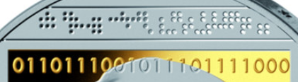
That is a fair assumption and if I were to throw binary code on a coin, I’d definitely embed some clever message, not too obfuscated to decypher.

Even with the assumption that there are missing bits, the total would be 220, again, not a number divisible with 8. That’s not to say it MUST be divisible with 8, but it is rather uncommon for uncompressed data to end with an incomplete byte.

But, let’s try to have another angle at this. Supposing that the text would be uncompressed and it would end-up at some point (regardless of the number of bits) to represent characters in a successive pattern (i.e. A = x, B = x+1, C = x+2 and so on), we should be able to observe that pattern in regular text because, as Shakira would say: “Bits don’t lie”.

So, I have taken a sample english text, converted it to binary and looked for pattern 110, for instance. And here is that pattern with differend bit paddings:

real text

You will see here that the 110 pattern tends to align when the padding reaches 8, and forms a nice vertical pattern in most cases.

Now, looking at our binary data searching for the same pattern (starting with a minimum padding of 5, since the alphabet requires at least 26 characters which need at least 5 bits of data):

challenge

Now, you see that the same pattern is all over the place, doesn’t align nicely as the text before did.

While this is by no means an exhaustive analysis of the data, by this alone, I am pretty sure that if the binary sequence contains textual information, it is encoded or compressed differently.

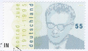
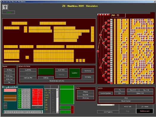
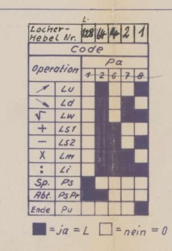
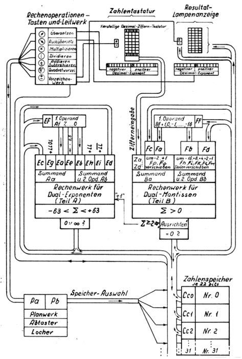
Also, given the work of Mr. Zuse, I’d expect that the binary code contains actual machine instructions instead of characters, but this too is a speculation.

I see 10 rows of 22 bits. Zuse’s first machine, finished in 1938, was the Z1, with 16 registers of 22 bits for binary floating point numbers. So, these are probably numbers: sign, exponent, mantissa. “(Donald Knuth attributes the invention of normalized floating-point numbers to Zuse)”

2 Likes

I think he also had infinity or NAN in there as well.

1 Like

Why would someone show 4 tracks when the first computer/calculator already had 8?
The first “computer” was the Z3. And that had 4 large rows of buttons. Not sure what medium that used.
The shown pattern of the punched tape/film might be found somewhere.
It resembles the Z1 punched film which had holes not in straight rows but every other row could have a hole in between like the 5 on a cube ⚄
Like the bow in the middle of the coin.
So we don’t know from which computer that is. Maybe not even a Zuse computer at all.
I now think that both codes are random data to just show 2 different representations of bits.
But 22 bits are at least correct.

Maybe I have to check patents and other publications.
Not sure if the coin designer is still alive. At least he must know that.
Some time ago I found some other non Z-computers like the SM1

I don’t know what it is, but I can count 40 columns of 4 bits, so we have 160 bits to play with. But it could be 44 columns if there are blank columns - and the pattern is not quite central which implies to me there are blanks.
image

Nice video:

There is also no guarantee that what we see is really contiguous bits, they could be left ends of some rows.

That being said, the coincidence of the 22 bits with Zuse floating point numbers is intriguing.

On a slightly off-topic point, I think it would have been of far greater effect if the central part of the coin would have been thinner and instead of zeros and ones they’d punched small holes respecting the binary pattern.
Now that would’ve been one cool coin in my book. :slight_smile:

So the input (keyboard) has 4 columns (x10 lines) and the output has 4 columns as well.
Maybe the top tape is related (the output) of the 0/1 field.
I found this interesting image of a Z3 simulator (I only have found the image)

Z3-Nachbau-2001

On the right are 2 fields. The left has 7+1 columns, but only 4 are used. The right has 14 columns. Both together makes 22 bits. So the 8/4 tracks are part of it.
Is it input or maybe a memory location, address or the exponent?
Probably the exponent. Although 7 bits, only 4 digits are entered in the emulation below.
It’s also the question where is the top (left or right of the coin)

I found another Windows emulator.
Zuse Z3

From the readme
S EEEEEEE MMMMMMMMMMMMMM
| \ \ \
| \ \ ------------------ Mantissa, 14 bits.
| ------------------------- Exponent, 7 bits.
±--------------------------- Sign, 0=positive, 1=negative.

Instruction Set:

The Z3 understood 9 different instructions. These included 2 instructions
for accepting input from the user and displaying results, 2 for reading and
writing the memory array and 5 arithmetic instructions. The oritinal
instruction names may have some meaning in German, but not a whole lot of
meaning to English speakers, therefore the assembler included with the
simulator will support both the original opcodes as well as a set of opcodes
that are more familiar to English speakers.

Original Opcode Function Bit pattern English opcode

  Lu         Read Keyboard     01 110000          IN
  Ld         Display Result    01 111000          OUT
  Pr z       Load Address z    11 zzzzzz          LOD
  Ps z       Store Address z   10 zzzzzz          STO
  Lm         Multiplication    01 001000          MUL
  Li         Division          01 010000          DIV
  Lw         Square Root       01 011000          ROOT
  Ls1        Addition          01 100000          ADD
  Ls2        Subtraction       01 101000          SUB

Hm… “P” seems to be a transfer instruction from and to memory and “L” is interacting with what seems to a be buffer register. These are also encoded in the first two instruction bits.

So we get:

L group (01):
u … peripheral in – ??? (Um-?)
d … peripheral out – Datum? Durchgabe? (announcement)
m … multiplication – Multiplikation / multipliziere
i … division – “d” is already taken, use “i” for Division / dividiere.
s1 … addition – Summe (sum)
s2 … subtraction – as above
w … square root – Wurzel (root, common short term for square root or Quadratwurzel)

We may have to refer to Zuse’s writing for “u” and “d”.
I guess, “d” must have been conceptually rather fundamental in order to assign it to the output instruction and not to division.
“w” somewhat proves that this is German and not, say, Latin (which would be “r” for radix).
BTW, this is borderline interesting, since the scholarly correct way of naming things would have been in Latin or maybe in Greek. So this is Zuse as an engineer (as opposed to a scholar).

P group (1x):
r … store (transfer to memory) – registriere or Register (register)?
s … load (transfer from memory) –??? (maybe just an iteration of “r”?)

I’ve no conclusive idea, what “L” and “P” may stand for, or if there’s any inherent meaning to it, at all. These may be generic expressions, as well.
We may associate “L” with Leistung (work), since there’s actual work done by these instructions, while “P” may be associated with a greater Plan (plan, program) as in Plankalkül. But I understand these neither as compelling nor conclusive.

I’m currently checking some original Zuse documents. I still haven’t found everything. I wonder why it’s so difficult.
L might stand for Locherhebel (punch lever) or Locher. There are arrows u,d (up down? but I found for Lu u=Übersetzen (see image 2). But for Ld Rückübersetzen , mabye De-… The result is decimal (like the input).
zuse
Konrad Zuse Internet Archive - Item id axU28RMNhK9wdaXV
Above original schematics. Note the bit pattern, note the manual change of the bit order. Note that there’s an additional instruction Ende: Pu.
Abt. = Abtaster, Abtastmagnet?


8. PC-Simulation der ZUSE Z3 von DL3NDR - DARC
Lu =Übersetzen (translate) Note there’s an additional instruction ± Vorzeichenwerk
P might stand for Planwerk, r maybe relay. or register
P maybe Programm. R =Rechenwerk, S=Speicherwerk?
Also here Abtaster, Locher
This should also be from original (reconstructed) sources, patent?
I’m still searching. I also have to run the emulator. And Z4 which might similar.

1 Like

By coincidence (searching for PLC stuff, again Google can’t find specific 70s stuff) I found a DIN standard 61131-3. Although it’s a modern PLC standard it derives from an older 80s standard that derives from an even older one.
I found all 4 characters: S setzen (set) R Rücksetzen, U Vorwärtszählen, D Rückwärtszählen.
Siemens STEP 7 still has S, R but instead U ZV and instead D ZR.

I think these are old electronics symbols and not invented by Zuse.
S and R are still on a symbol for flip-flops.
S+R are the same in English and German.
U+D not. So obviously English (counting) upwards , downwards (matching the arrows).

Maybe I will check some more manuscripts from Zuse (Z3 only) but I think there are too many pages and hard to read handwritten pages.

I found another manuscript, hard to read
L is obviously Leitwerk (easier to read on earlier pages, also on my pic 2)
U übersetzen
D Rückübersetzen (not stated here what D stands for)

Konrad Zuse Internet Archive - Item id YjBueilZYhDx7qs

This image linked below, full schematics is also very interesting ,
P probably stands for Planwerk.
The D from Rückübersetzen might come from Drehwähler
L Leitwerk here is Leitrelais.
Also detailed description of the holes on the film (far right) and more info

Konrad Zuse Internet Archive - Item id qQWX0ccruZBdzMrp

It has been before our eyes the entire time!
The punched film seen in the document above (Film como soporte digital | IDIS) isn’t in 8 tracks, but in pairs of 4 tracks, the lower one slightly offset. The legend gives it away:

1 1 0 0     Abrufen Speicher Nr. 2
 0 0 1 0    (retrieve memory register No 2)

0 1 0 0     Multiplizieren
 0 1 0 0    (multiply)

1 1 0 0     Abrufen Speicher Nr. 10
 1 0 1 0    (retrieve memory register 10)

0 1 0 0     Addieren
 0 0 1 1    (add)

1 1 0 0     Abrufen Speicher Nr. 6
 0 1 1 0    (retrieve memory register 6)

0 1 0 0     Dividieren
 0 1 0 1    (divide)

0 1 0 0     Vorzeichenumkehr
 1 0 1 0    (sign reversal)

1 0 0 0     Speichern auf Nr. 10
 1 0 1 0    (save in No 10)

Mind that this not exactly like the Z3.

The text above this provides some context:

Durch die vorigen Rechenschritte stehen im Rechenwerk die Zahl e [und| in den Speichern Nr. 2 6 10 die Zahlen b c d.

Nächster Rechenschritt:

       a . b + d
e = - –––––––––––  -> Speicher Nr. 10
           c         (e ersetzt dort d)

translated:

After the previous steps, the accumulator holds the number e and memory registers 2, 6, 10 hold the numbers b, c, d.

Next step:

        a * b + d
 e = - –––––––––––  -> memory register 10
            c          (e replaces d)

So it should be perfectly possible to represent this in 4 rows, like,

x. .. xx .. x. .. .x xx
x. xx x. x. xx xx x. ..
.x .. .x .x .x .. .x ..
.. .. .. .x .. .x .. .x

l2 m  l1 a  l6 d  rs s1
o  u  o0 d  o  i  vi t0
a  l  a  d  a  v  sg o
d  t  d     d      n r
                     e

or, if we want to mirror the film more closely, we’ll have to flip this vertically, like

.. .. .. .o .. .o .. .o
.o .. .o .o .o .. .o ..
o. oo o. o. oo oo o. ..
o. .. oo .. o. .. .o oo

But the latter doesn’t seem to be what the banner is doing. This seems to have the leftmost column (#0) on top, like our first version.
But, I’m not so sure that this is Z1 code, at all, since it looks like a much more complex instruction set.(E.g., there are codes with the first 3 bits set.) Still, it could be any of the Zuse machines using the 8-track (i.e. pairs of 4 track + offset) 35mm film format.

1 Like

LOL, reading through these comments got me thinking of this homage to “Tron” from many years ago.

At the end, Bit sends out a “message” (“Yes, yes, no, yes, …”) I tried deciphering it, and it just came out garbage. :slight_smile: