I also considered asking ChatGPT. But I think it would take many many more years for a KI to be helpful to all the problems. Currently just fed by the web.
I found some tools in hexeditor Okteta. Also including bit reversal. But no plausible code either.
I have read again the manuals of my device and found some new facts.
-The default size of the RAM card, even of the PLC is just 256 words.
So I have 8+1 ROMs and 2 different kinds of RAM on both devices each. The on-board RAM might just be a buffer. And the card on my device acts more like a disk.
The main system ROM and RAM is that of the PLC. I have more details, and my device has more control about that, than on its own (eg registers, display).
-There’s a regularly signal interaction when attached to the PLC (triggered by that) to make sure it’s still attached. Resides at 7700-7777 (on PLC?). Maybe the 9th ROM has something to do with that.
-There are 2 functions to search the written code on the RAM cartrige for address instructions and for a specific functional unit. That works without a PLC, but needs a cartridge and a TTY attached.
As my device has a syntax check and can disassemble, the mnemonics must be stored and their condition codes. The longest one is SONST and must be stored somewhere somehow.
The PDP8 CPUs have to simulate the instructions of the PLC (at least on that). I now focus on those instructions and on the function my device has. Registers are maybe just on the PLC.
The Festo instructions are very simple and these are stored as 6 digit commands. And stored/displayed reversed. But not sure how and where these are stored in PDP8 style.
654321
xyabcd

.WENN ESB FEL  (Wenn Eins-Signal an Fehler)
0      1  0077
 DANN LOE ANZ  (dann lösche Anzeige)
0      2  0050
This is a typical set of 2 commands. If signal 1 at error flag, then delete display (of the PLC).
The digit on the left can be bit 0 or 1. 1 eqals the keys Außerdem and sonst (furthermore, else).
Digit 5 is the instruction 0-7. (0 signal, 1 signal, delete, set, load, with content, with address, as decimal). The other 4 digits are either a functional unit, an address or decimal value.
An if condition can, I think just read a 0/1 signal from different units. The longest command has 4 mnemonics but still 6 digits
;WENN ...       (furthermore, if)
1
 DANN LAD ZAL 07  ;then load counter #7
0      4   3  007
      MDZ     123  ;with decimal 123 (converted to octal)
0      7      0173
      MIV     ZSK  ;with 0.1 sec clock
0      5      0031
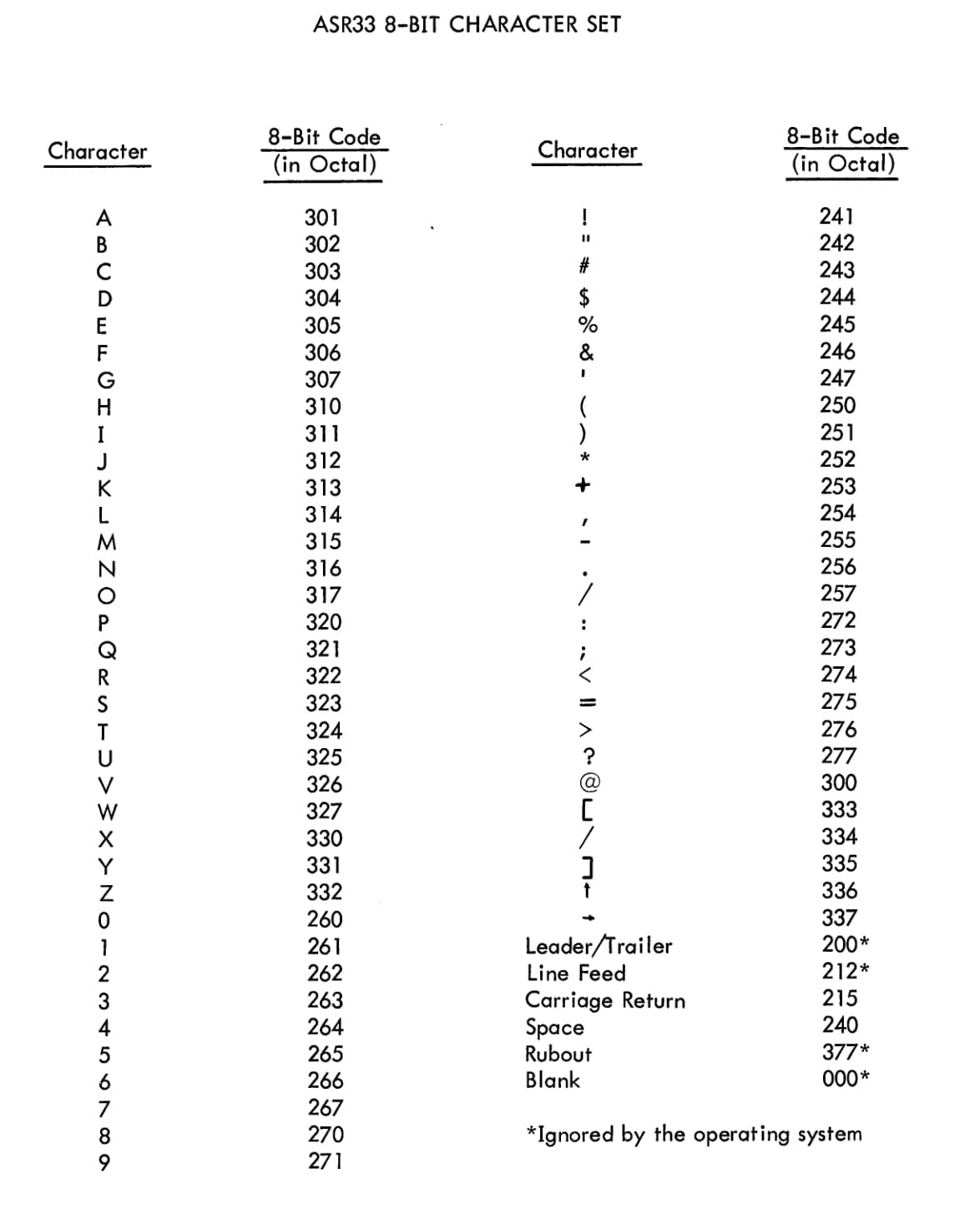
There must be a conversion routine somewhere. The display can show decimal and octal values + E, F, _ etc encoded as 8 bit BCD 2/3/3 bits. In the manual there’s a table, but I think it’s not stored as table.
And what about condition codes? The only allowed instruction with the display is delete.
How is all this usually stored on other computers? Any other suggestions how to go further? I’m still stuck on the right ROM merging. The PLC has 4 pairs of 2.