If you have the code to implement your function, converting that to a lookup table is trivial, and chances are the table will be smaller than the code, especially if you restrict it to 6 bits and handle the other two separately, eg return (n&0xC0)|rev6[n&0x3F];
I guess, everyone has a comfort zone, esp. when it comes to doing something “brute force” in an unfamiliar and poorly understood language.
Mind that
(n&0xC0)|rev6[n&0x3F]
is quite a complex expression, if you’re not familiar with C or similar languages.
Personally, I’m feeling comfortable with a loop.
E.g. (use any type you want, here using int for generality),
int rvsOctet(int x) {
    int r = 0;
    int i;
    for (i = 0; i < 8; i++) {
        if (x & (1 << i)) r |= 1 << (7-i);
    }
    return r;
}
I also considered asking ChatGPT. But I think it would take many many more years for a KI to be helpful to all the problems. Currently just fed by the web.
I found some tools in hexeditor Okteta. Also including bit reversal. But no plausible code either.
I have read again the manuals of my device and found some new facts.
-The default size of the RAM card, even of the PLC is just 256 words.
So I have 8+1 ROMs and 2 different kinds of RAM on both devices each. The on-board RAM might just be a buffer. And the card on my device acts more like a disk.
The main system ROM and RAM is that of the PLC. I have more details, and my device has more control about that, than on its own (eg registers, display).
-There’s a regularly signal interaction when attached to the PLC (triggered by that) to make sure it’s still attached. Resides at 7700-7777 (on PLC?). Maybe the 9th ROM has something to do with that.
-There are 2 functions to search the written code on the RAM cartrige for address instructions and for a specific functional unit. That works without a PLC, but needs a cartridge and a TTY attached.
As my device has a syntax check and can disassemble, the mnemonics must be stored and their condition codes. The longest one is SONST and must be stored somewhere somehow.
The PDP8 CPUs have to simulate the instructions of the PLC (at least on that). I now focus on those instructions and on the function my device has. Registers are maybe just on the PLC.
The Festo instructions are very simple and these are stored as 6 digit commands. And stored/displayed reversed. But not sure how and where these are stored in PDP8 style.
654321
xyabcd

.WENN ESB FEL  (Wenn Eins-Signal an Fehler)
0      1  0077
 DANN LOE ANZ  (dann lösche Anzeige)
0      2  0050
This is a typical set of 2 commands. If signal 1 at error flag, then delete display (of the PLC).
The digit on the left can be bit 0 or 1. 1 eqals the keys Außerdem and sonst (furthermore, else).
Digit 5 is the instruction 0-7. (0 signal, 1 signal, delete, set, load, with content, with address, as decimal). The other 4 digits are either a functional unit, an address or decimal value.
An if condition can, I think just read a 0/1 signal from different units. The longest command has 4 mnemonics but still 6 digits
;WENN ...       (furthermore, if)
1
 DANN LAD ZAL 07  ;then load counter #7
0      4   3  007
      MDZ     123  ;with decimal 123 (converted to octal)
0      7      0173
      MIV     ZSK  ;with 0.1 sec clock
0      5      0031
There must be a conversion routine somewhere. The display can show decimal and octal values + E, F, _ etc encoded as 8 bit BCD 2/3/3 bits. In the manual there’s a table, but I think it’s not stored as table.
And what about condition codes? The only allowed instruction with the display is delete.
How is all this usually stored on other computers? Any other suggestions how to go further? I’m still stuck on the right ROM merging. The PLC has 4 pairs of 2.
This looks much like a microded instruction set.
I.e., we have an istruction “LAD” and the first octal digit of the operand specifies a mode, here “3” for a counter, the rest of the oprand specifies the source/target (counter 7). Mind that digit posions may matter, e.g., there are only 7 counters and they are always given in the last digit, but for code “4” (in place of “LAD” = 7), the argument would always be in the second-last digit, etc. (Expect binary patterns for microcodes, they may be well be allowed to be combined into a single instruction for a respective group. Hence dedicated digits for arguments.)
Regarding conditions, I do not see a clear pattern in your examples. (Is it “0” for a first “WENN” [if] and “1” for “;WENN” [else if] – possibly with further increments –, followed by any number of “DANN” [then]instructions prefixed by “0”? But how do we switch back to a new, first “WENN”?)
Instruction registers are usually on a CPU, but the 6100 has only it’s own one.
Strange, that an instruction consisting of 1 bit+1Byte+1 octal word. When storing as words it has to be 2 words.
Counters have a maximum of 77 (octal). These are 3 digit decimal counters stored at 30xx-3077 running up or down (can be changed).
But I think the last 4 digits are stored as one word (in order, reversed) as it also can be an address or even decimal values (stored as octal).
The question about the conditions is a good question as both .WENN and DANN starting with 0. And you can add any number of instructions. You can also use OR and (neg) brackets (which have one fixed instruction each). Otherwise it’s an ‘and’.
Else is SONST, and starts with 1, same as ;WENN (furthermore).
Each line of SONST also starts with an 1. And when there’s a 0 you have a new .WENN instruction.
I think it also depends on the instruction. A …(then) delete display can’t be an if condition, so has to be then. You can’t just delete the display but need an if condition first.
Reading for a 0 or 1 signal can just be an if condition. The rest is 0 then or 1 else. If there’s an if condition with 1, then it has to be ;WENN.
And of course a user should only enter valid code.
For complicated, nested code and code segments, there are pointers and maybe flags, but all on the PLC.
On conditions without brackets, the device uses the disjunctive normal form.
All code can be drawn as ladder logic.
0 .WENN
0 (and)
010001 or
0 …
0 DANN
1 SONST
1 … (and) still SONST
0 .WENN
I have to carefully check the dec-ii-rom disassembly.
This somewhat reminds of a kind of instruction layout that was somewhat popular on large one-of-a-kind systems in the 1950s (I forgot the name for it), This came with a very stringent and systematic design, where each instruction started with an array of bits, specifiying if it is an condition, what kind of condition it is, if it is negated, what kind of instruction it is, etc (this could be up to 10 bits). This is somewhat like reducing this to the bare minimum, by making it always a condition and having just a bit for the branch, we’re in.
(Zemanek’s “Mailüfterl” would be an example for this, see https://norbertkehrer.github.io/mailuefterl.html.)
I assume that this is the design for all PLCs. Not sure about the recent ones.
I haven’t checked the dec-ii disassembly, yet.
Instead I found a dec papertape called reverse assembler and other tools.
After having loaded this papertape, you can read another one and the result will be printed out.
I couldn’t manage to load both papertapes on the online emulator and don’t know how to enter the settings. I tried to input the 2nd tape as BIN and text file and tried all settings but it won’t read it.
I have to try this on the Mac Emu or SIMH.
I’m interested in the name of those large systems. I only found stored-program computer. Or is it a German term? In Germany they would maybe just titled Rechenmaschine, maybe a patent.
I believe, its a double name (two persons’ names or maybe a place and a person?) It may be well Dutch. Some systems in the Netherlands were prominent examples (I think). I really have forgotten the name, as it doesn’t turn up often and it’s also, let’s say, “on the outskirts of my expertise.”
(I find it quite difficult to find any references on things like this on the Internet, lately, if you do not know the exact term. I’ll have to look up some old files, where this may be included. I remember a discussion about this, we had on the old G+ Vintage Computing community.)
Is it a nickname? Than it’s not that important. Otherwise it should be easy to find or maybe someone else knows.
The Reverse Assembler worked on Mac (emu on emu).
Output on HiSpeed punch took ~5 seconds
Output on LoSpeed TTY took 5 seconds per instruction/line. So extremely slow.
Mode 1 looks like a disassembly list.
Mode 2 like a run.
The output punch is a sympolic tape for the PAL III assembler and in an unknown binary format.
The decmate-ii rom disassembly is very interesting.
Obviously 8 bits (not bytes) are splitted up onto 2 ROMS
and 2x4 bits on another ROM make 12 bits.
I don’t have 3 ROMs but 8, but I do have 3 RAM chips.
Can anybody explain that, is that plausible in my case and how to easily merge bits from different ROMs?
/ DECODED AND DISASSEMBLED BY CHARLES J. LASNER.
/	LAST EDIT:	02-DEC-1991	02:00:00	CJL

/	MAY BE ASSEMBLED WITH '/J' (PAL8 '/F') SWITCH SET.

/	THIS IS THE CODE  USED  IN  THE DECMATE II PRIMARY CONTROL ROM.  IT RESIDES IN
/	THREE 2716 PACKAGES  KNOWN  AS  E113,  E114, E115.  THE THREE ROMS ARE ENCODED
/	INTO  A 12-BIT IMAGE  OF  AN  ENTIRE  FIELD  IN  THE  PARTICULAR  ORGANIZATION
/	ILLUSTRATED BELOW.  FOR ALL  ROM  CONTENTS:  0.X=BIT X IN THE SPACE 0000-3777,
/	4.X=BIT X IN THE SPACE 4000-7777.

/	E113:	0	1	2	3	4	5	6	7

/	BIT:	0.0	0.1	0.2	0.3	0.4	0.5	0.6	0.7

/	E114:	0	1	2	3	4	5	6	7

/	BIT:	4.0	4.1	4.2	4.3	4.4	4.5	4.6	4.7

/	E115:	0	1	2	3	4	5	6	7

/	BIT:	0.8	4.8	0.9	4.9	0.10	4.10	0.11	4.11

/	THIS IS THE ASSEMBLY OF THE RELEASED ROM SET KNOWN AS 358E2, 359E2, 360E2.

/	WHEN THE DECMATE II IS FIRST POWERED UP, ROM CONTROL IS ENABLED FOR ALL DIRECT
/	(IF)  AND  INDIRECT  (DF)  REFERENCES  TO CP MEMORY, THUS THE  CPU  STARTS  AT
/	ROM-BASED ADDRESS CP07777.  THE ROM CODE MOVES A LOADING PROGRAM  TO PAGE ZERO
/	OF  THE CORRESPONDING RAM IN FIELD ZERO OF CP MEMORY, WHICH IS  THEN  STARTED.
/	TO ACCOMPLISH THE INITIAL MOVE OF THE LOADER, THE DF CONTROL IS CHANGED TO RAM
/	WHILE RETAINING IF CONTROL IN THE ROM.

/	THE LOADER MOVES THE BULK OF THE ROM CODE TO CP FIELD SEVEN AND THEN STARTS IT
/	THERE.  ...
The full disassembly is here, but it’s very long. Well documented, but some few parts are assumptions.
By coincidence I found that there’s a new version of the Mac emu (but I think only for MacOSX, so I can’t use it) which doesn’t need conversion for DECtape.
I found again the 2/3 encoding (I mentioned before) which should be the most common encoding for BIN files (but mainly used by OS/8). Probably it’s the same as the encoding above, 3 bytes are written in 2 words
aaaaaaaa          ccccaaaaaaaa
bbbbbbbb          CCCCbbbbbbbb
ccccCCCC
I think it’s mainly used on text files. Maybe only on some ROMs or ROM sections (after the empty bytes ?)
The only notable external tool is PUTR (DOS only). That should be able to convert an ASCII file this way. I’ve tried it yesterday, the result was not as expected. I think the input file was not plain ASCII and maybe I’ve chosen a wrong disk format or switch.
Input 023 0750 30 077 , output 0.2. .0.5. .3.0.0.7. .0.3. .2.3.0.
I would need it to be converted the other way anyway.
I have to try more software on PDP8 paper tape or even PDP11 emulators/tools.
I also found a PDF with another ASCII table.
‘A’ should be octal 0104, B 0204… , 0= 0003, 1= 0103.
The PDP-10 should have a slightly other encoding.
DECtape has another encoding 11:1
Have a look at this example from the manual for the PAL-D assembler for the PDP-8:
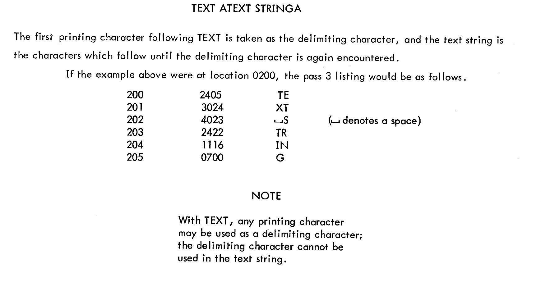
Mind the note on the 6-bit trim here:
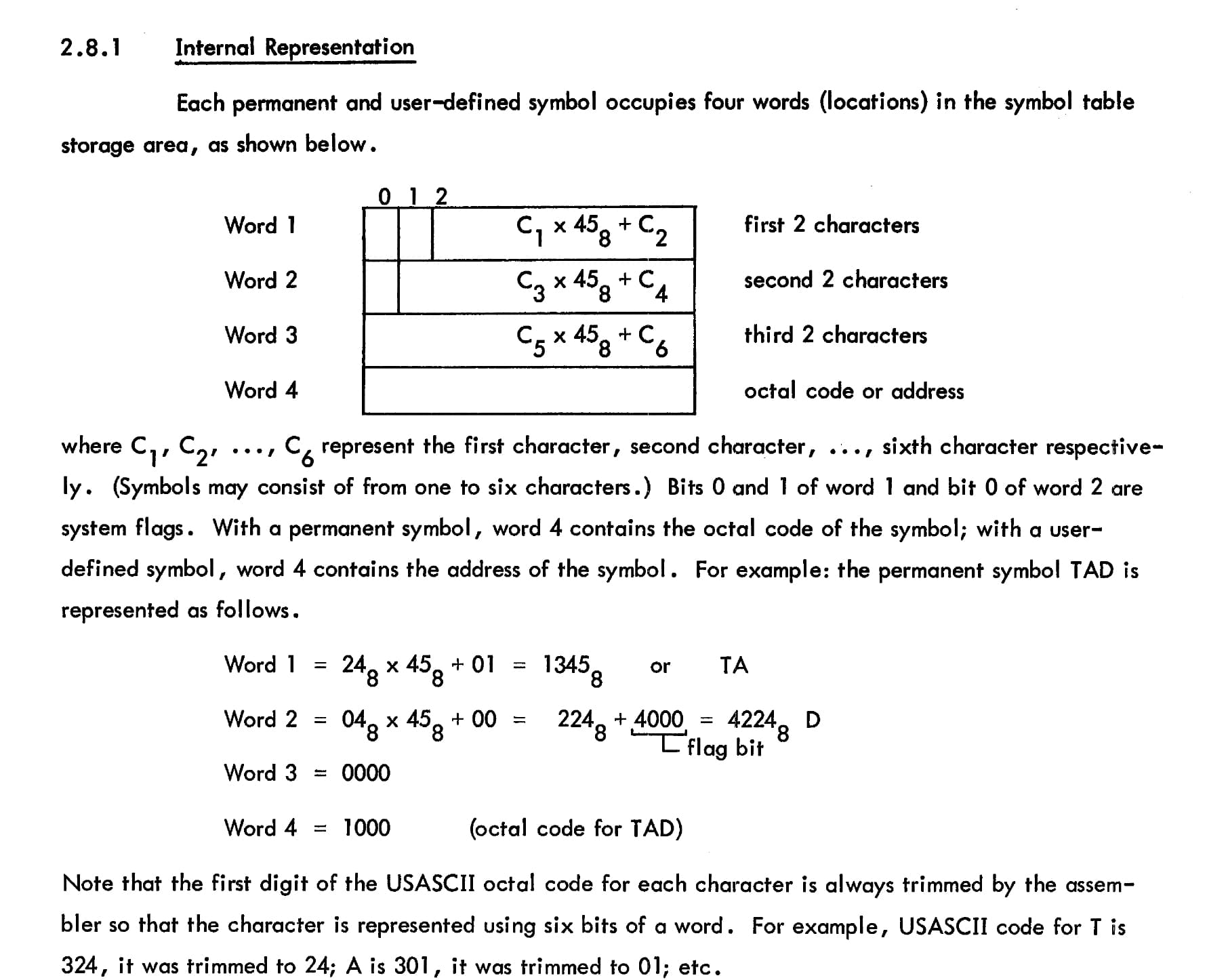
(Source: http://www.bitsavers.org/pdf/dec/pdp8/software/DEC-08-ASAB-D_PAL-D_ProgRef.pdf)
The character encoding is the same for PAL-D and FORTRAN on the PDP-8:
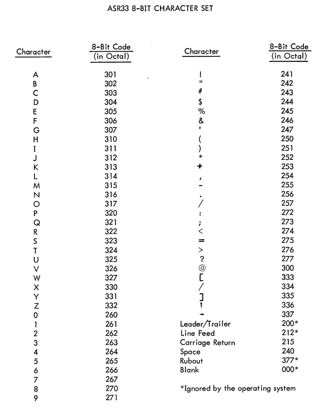
Mind that there are really just a few collisions with the 6-bit trim applied (namely with characters at the end of this table, starting with “@”.) “6-bit trim” really means, we ignore the first, leading octal digit.
1 Like
P.S.: Generally, for anything regarding the PDP-8, have a look at the “Small Computer Handbook”:
http://www.bitsavers.org/pdf/dec/pdp8/handbooks/SmallComputerHandbook_1970.pdf
Yes, this is the standard encoding for text, A=1. And usually there’s only one column (last 2 digits of the word). This ASCII representation is displayed on the output of the online emu and I also have added this character set on my conversion table for my hex editor.
I’ve checked this on all my ROM combinations but as I haven’t found any useful text, I want to try other encodings.
My decice can’t display ASCII, except for E, F, _. So this is just for a disassembly export to a printer.
I found a 1998 toolset called dumprest by David Gesswein with c codes for both ways of the 2/3 encoding. Originally, this is for dumping or restoring a td8e tu56 DECtape file via serial port from original hardware.
There are 3 different DECtapes, I assume this is for 12 bit.
I first tried to output that on stdout instead of ttyS17, but that didn’t work.
So I’ve started to change the code.
I want to read 3 bytes and output as 2 words. I use dumptd8e.c
The input file is ‘dat’. (Was a test code as output).
The output file is that, someone enters.
Leader and trailer has to be removed.
The DECtape header byte 1 / block flag must be FE in hex (instead of DECtape\n in ASCII.
After that there has to be the checksum probably before each of the blocks (129 words each) as hex bytes 3 and then 2. The calculation is different than usual. Maybe I have to remove that.
I somehow have to mix both files. Count 128 is the amount of blocks.
file: dump (buffer 200 (serial, amount of bytes? in dec?), tmp 0, later a for loop)
count = -1;
   block = 0;
   byte = 0;
   while(!terminate) {
      c = ser_read(fd,(char *)buf,sizeof(buf));
receive, but reads 2 words, buffer 3, tmp 2, later if and while
count = 128;
   block = 0;
   readsz = 0;
   while(!terminate) {
      if ((rc = fread(temp,2,2,in)) < 2) {
The serial read in c is different than fread (error when replaced: too few arguments to function fread).
Although I have both codes, it’s difficult for a beginner to replace the right stuff.
Snippet 2 has 2 different variables and I have to read 3 bytes instead of 2 words.
Both files have just one file opened and non of them closed, user has to CTR c to stop the serial traffic.
I have to rewrite it from scratch, properly open and close 2 files etc.
Will take many, many hours for a beginner. Not sure if I will be successful.
Hum, if this is just a 7 segment display, the program may use the usual BCD codes for this?
Yes, the display has a BCD encoding (forming one word) but it’s very complicated. 4 Locations, each with a different address, one has 4 digits and can just display octal values. 3 can display decimal and/or octal values, 2 of them can display special characters and 2 other ones work together. There is a table in the manual ,but I assume it’s not stored as table in the ROM.
E9 7777
*F9 999
I also mentioned that on my other thread
Help reading EPROM (Intersil IM6654A) and analyze firmware - #4 by mainframetom
A new fact is that the 3 digit decimal position in fact holds a value of 4 digits.
I can only read and write to the display of the attached PLC CPU card (which has the same style) so at least the addresses are different.
But I’m mainly searching for the mnemonics, being printed out. If I found these, I will be sure to have the correct ROM merging and then also the right PDP code.
I think, I even have found the location at 2000o the 3 character words are surrounded by @, but the 3 characters are wrong. DIV sounds plausible but isn’t a mnemonic. The @ seems correct.
So either another encoding or even encryption. I’ll now try to write the c code for the 2/3 encoding. I would need a program, searching for text while scrambling bits and bytes in all possible combinations.
This sounds like Radix-50 encoding, there should be some resources with code examples out there to leverage.
Radix-50 was suggested on the other thread and I think, I haven’t tried that one, yet. I found that that wasn’t used on PDP-8 and according wikipedia it’s 36, 18 or 16 bits. (16 bits is possible).
I also found a Radix-40 (or was it 45? but could be the same as 50o is 40 in dec) eg. three chars per 16-bit word.
I can’t test this as character set with representation of one byte. So I would need a conversion code.
After 10 hours work of trying the 2/3 encoding (see above) on c with many errors, I tried it to be very simple.
That is my final result. Reading of 3 bytes worked. No errors, no warnings. But the output is wrong. I also tried printf %4d (needs to be 12 bits). 13 3D 18 should be 0423 4075. Who can help? Is there a conversion missing? Or can’t it be done this way at all?
printf("%02x %02x %02x\n", (int) buf[0], (int) buf[1], (int) buf[2]);

      temp[0] = (buf[2] << 4 | buf[0] >>8) ;
      temp[1] = (buf[2] >> 4 | buf[1] >>8) ;
      printf("%04o %04o\n", (int) temp[0], (int) temp [1]);
The original code is this (the other way). Not plausible to me
if (block % 5 == 0) {
            printf("Block %d\r",block);
            fflush(stdout);
         }
      }
         /* Send 2 words as 3 bytes */
      chksum += temp[0] + temp[1];
      buf[0] = temp[0];
      buf[1] = (temp[0] >> 8) | (temp[1] << 4);
      buf[2] = (temp[1] >> 4);
      ser_write(fd,(char *)buf,3);
Update: Radix 50:
Here’s a conversion code
-Intro to System Software, Chapter 3
Here it says that it was only used for filenames
A codetable
| First | Second | Third | First | Second | Third | |||
|---|---|---|---|---|---|---|---|---|
| char | char | char | char | char | char | |||
| Space | 000000 | 000000 | 000000 | T | 076400 | 001440 | 000024 | |
| A | 003100 | 000050 | 000001 | U | 101500 | 001510 | 000025 | |
| B | 006200 | 000120 | 000002 | V | 104600 | 001560 | 000026 | |
| C | 011300 | 000170 | 000003 | W | 107700 | 001630 | 000027 | |
| D | 014400 | 000240 | 000004 | X | 113000 | 001700 | 000030 | |
| E | 017500 | 000310 | 000005 | Y | 116100 | 001750 | 000031 | |
| F | 022600 | 000360 | 000006 | Z | 121200 | 002020 | 000032 | |
| G | 025700 | 000430 | 000007 | $ | 124300 | 002070 | 000033 | |
| H | 031000 | 000500 | 000010 | . | 127400 | 002140 | 000034 | |
| I | 034100 | 000550 | 000011 | Unused | 132500 | 002210 | 000035 | |
| J | 037200 | 000620 | 000012 | 0 | 135600 | 002260 | 000036 | |
| K | 042300 | 000670 | 000013 | 1 | 140700 | 002330 | 000037 | |
| L | 045400 | 000740 | 000014 | 2 | 144000 | 002500 | 000040 | |
| M | 050500 | 001010 | 000015 | 3 | 147100 | 002450 | 000041 | |
| N | 053600 | 001060 | 000016 | 4 | 152200 | 002520 | 000042 | |
| O | 056700 | 001130 | 000017 | 5 | 155300 | 002570 | 000043 | |
| P | 062000 | 001200 | 000020 | 6 | 160400 | 002640 | 000044 | |
| Q | 065100 | 001250 | 000021 | 7 | 163500 | 002710 | 000045 | |
| R | 070200 | 001320 | 000022 | 8 | 166600 | 002760 | 000046 | |
| S | 073300 | 001370 | 000023 | 9 | 171700 | 003030 | 000047 |
Next to the above problem in c coding, I tried a RAD50 conversion.
int i;
int* c1, c2, c3;
printf("%02x %02x %02x\n", (int) buf[0], (int) buf[1], (int) buf[2]);

      c1 = (buf[0]);
      c2 = (buf[1]);
      c3 = (buf[2]);
      void unpack( int i, char* c1, char* c2, char* c3 ) /*original code */
      {  *c1 = ascii(i / (40*40));         /*original code */
         *c2 = ascii((i /40) % 40);
         *c3 = ascii(i %40);
         printf("%s %s %s\n", c1, c2, c3);
Now, I don’t have any warnings; but the output is empty.
I know that *c1 is a pointer. Not sure how to declare it c1 or *c1 (int, *int, char, *char). I think I’ve tried everything. Or should it be an array?
I’m also not sure how the input should be. I want to unpack the rad50 stored as characters in 3 bytes. Or is that packing? (I’ve also tried this.)
And the RAD50 value can be 6, 5 and less digits down to 1 like ‘0’ as shown on an RT-11 directory header.
Edit: The output should be up to 3 characters from an unknown amount of digits (1-6) derived from 2 bytes (16 bit)? Both packing and unpacking routines have an input of 3 characters. Maximum rad50 is 63999 (dec?) from input 9 9 9.
SWA= 75131. P=62000, 1XM= 142615, space=0. Obviously these are octal values added depending on their position from table above.
Can someone please help me with both problems?
I have manually decoded mnemonic LAD = 45454o = 4B2C hex. I’ve searched all my ROM combination without any result. So RAD50 is obviously out.
The 2/3 encoding can’t also be the case on my original file (without cross merging) as no Hex value is above 3F. But I do assume cross merging.
Another way is that every single ROM is already merged from 2 half sections, but 16 ROMs are unlikely, rather 4 or 2. Maybe each ROM is flipped/inverted?
Another progress, from another approach.
I’ve checked again in the manual how the printouts work. There are 3 kinds of printouts, all starting with different characters, probably from German terms.
/S (done by the PLC, but my device maybe can do that as well in remote-control mode) different widths, PLC also can print comments
/D (memory dump without mnemonics)
/L (reverse assembly list with mnemonics) like this
/L 00000-00003 S: 0000176022
00000: 011001 .WENN ESB EAS 1
Top: start and end addresses (octal) then S: and a checksum, probably just the right 6 digits
Below: Adress (octal), Festo instruction (octal), mnemonics, some with operands/adresses (some values are decimal eg counters).
I found all 3 /S/D/L characters and S: in my first (non-cross merged) file (after having it fixed twice) and values pointing to that locations.
One string is like this
/L X: X: X, ;C US DL. (if x is a placeholder for 00000 than that’s it, US and DL probably not involved).
The printout is sent as 7 bit ASCII (slightly different than DIN standard for the parity bit). I think the 6100 CPU has an implementation for conversion.
I wonder how this mixed line of Sixbit encoded characters, octal and decimal digits and probably other encoded characters work.
The pdp8 code of this file is not that plausible when starting at 0 or 200. But more plausible when starting at the address stored in word 0.
And that file just has 12 bit values stored in the bytes. Still unclear the 2 empty sections and the missing mnemonics.