When I joined, I mentioned that was building a retrocomputer of my own. It’s a reached a good point, so here it is: Jeff's Occasional Blog: YARC (Yet Another Retro Computer). The blog post contains links to all the design artifacts on Github. My blog is not monetized and never will be if I can help it. Hope you find it interesting!
9 Likes
Wow. That’s… wow.
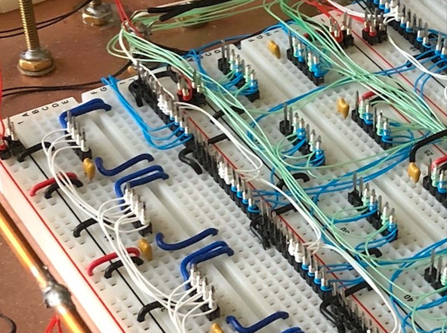
Can you explain your bypassing technique? Also, in the detail of your construction method, what are the thicker gauge grey wires?
Bypassing … decoupling? Power supply decoupling? I was not consistent about it at first, but in later sections I was careful to always connect a row of ground pins next to any breadboard row that had power. I put 0.1uF ceramic capacitors into the breadboard as close as possible to the power supply pin, usually 1/10 of an inch (breadboard spacing). This is not ideal, because breadboards have higher connection resistance than soldered connections. But it was the best compromise. I have seen other people use sockets with capacitors soldered across the power and ground pins at the corners, which is probably a better answer except you need all those sockets.
The thicker gauge gray wires you see are typical 22ga. breadboard wiring–just wires with stripped ends stuck down into the board. I used more of that type wiring at first, so the memory subsystem has a lot of breadboard wiring. But wire-wrapping was much faster so in the end I used almost all wire wrap except for the power and ground. These are always 22ga breadboard wiring (the short red and black wires).
The wire-wrapped connections are made to single-pin headers inserted into the breadboards. These are standard 0.025 inch square posts which are exactly what is needed for 30ga. wire-wrapped connections.
Let me know if I misunderstood you or my answers were not clear.
Thanks for the detail photo. I really like the wire-wrap on the top side construction technique; I used a similar one on my last project:
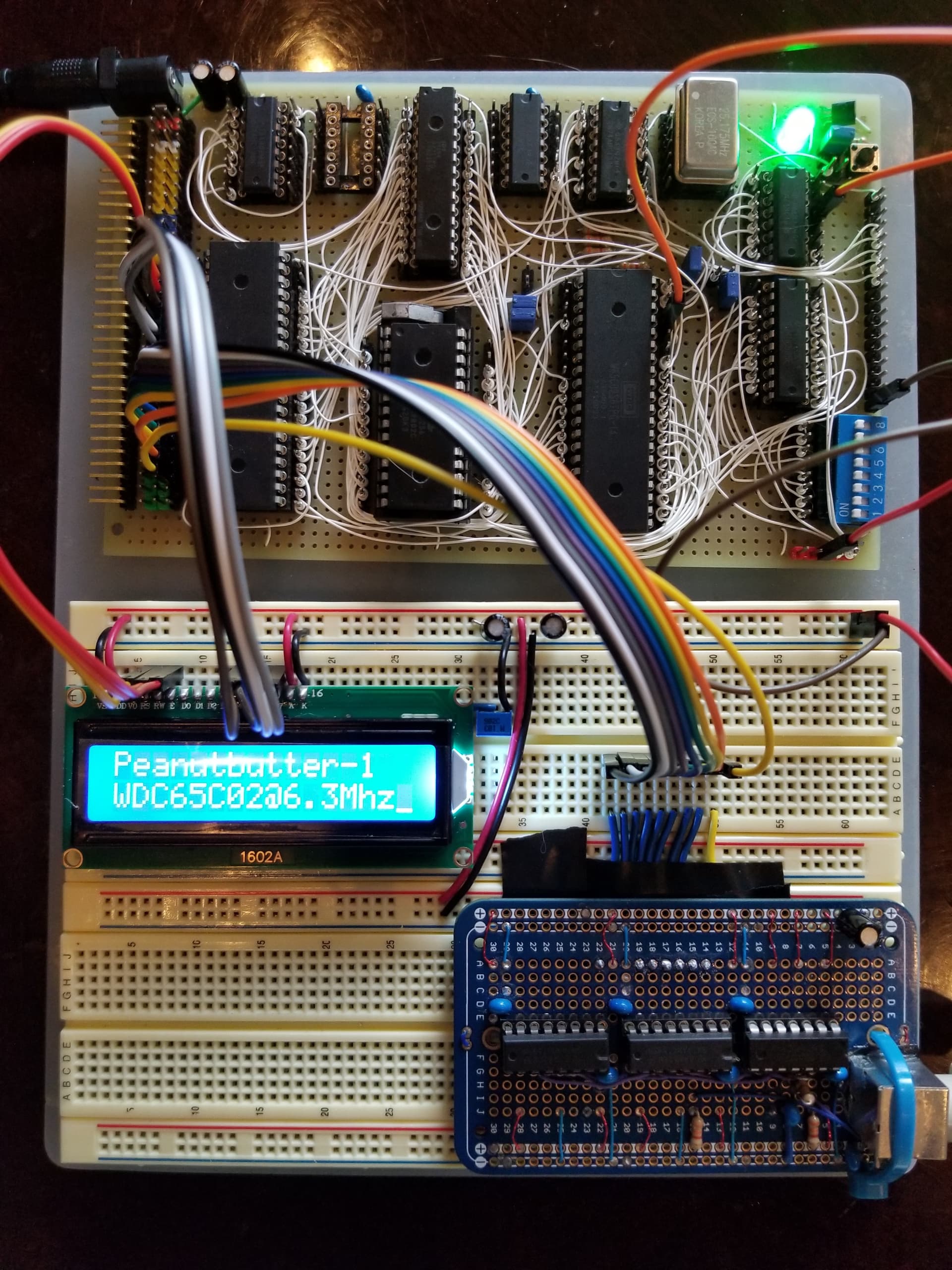
But yours is so tidy!
Yes, decoupling! Every time I do a project on breadboards I do a different decoupling / ground return network, but I haven’t settled on a method I really like yet. There are some really enormous breadboard projects out there that operate at high speed, but my projects always seem to hit a limit at about 4 breadboards where they just get too noisy to function.
2 Likes
Well, you could try the ground plane approach - just buy a big copper-clad board (I bought 1’ square copper-clad boards from Mouse for maybe $20?). Figure out where you’re going to put the breadboards and leave spaces. Drill through the copper and put in a small copper bolt, solder it to the copper cladding and solder the nut to the bolt. Stick down the breadboards. Then solder wire-wrap wires to the bolt and wrap the other ends to posts in the ground strips of your breadboards.
Regarding neatness: it looks good, but it doesn’t necessarily give the best results. The hardware is working pretty well, but gathering signals together into bundles sort of ensures maximum crosstalk.
1 Like
There are often discussions on the 6502 forum about power and ground, and decoupling, and ground planes. One of the crucial ideas is return currents - see for example here. (Which is to say, it’s all very well to have a large area of grounded metal, and that might act as an RF shield, but it won’t help with ground bounce unless it can carry return currents.)
1 Like
All the discussions about decoupling, ground bounce, copper fills vs. ground planes are right and valid and worthy of studying - and have been studied for decades if not approaching major fractions of a century now.
And there are also people like me who seem to get away without doing much in the ways of all that and build a 16Mhz 6502/65816 system on Stripboard then move it to a simple double-sided PCB where it continues to work at 16Mhz.
My excuse is that I don’t have the test equipment to tell it (or me) it’s not, or should not work, so it does… ![]()
-Gordon
1 Like
Hee hee - do you at least have chip-local decoupling caps, and an electrolytic near the power connection to the board?
1 Like
I do have that, at least.
On this subject there was an interesting video made by EEV Dave a while back where he used some very posh test kit on the Gigatron board and applied the “Muntzing” technique to it by slowly snipping off each decoupling capacitor one by one and tested the results. The board eventually did fail, but he said it was most likely due to him shorting something out while he was removing the caps with the power on…
In a subsequent video he re-designed the board as a 4-layer one and re-checked the noises, emissions and so on - and yes, signals were cleaner and overall the board did radiate less, so in some cases it may well be worth it, but but simple hobby projects ???
-Gordon
Regarding decoupling, there may be a bit of cargo-cult (or, tradition) from the TX-0 involved, especially, since slower computers seem to be robuster as they should be, even without this.
It comes down to driving a computer from a central power supply, with early, fragile transistors. (“Fragile” as in “Oh, I touched my hair and then the transistor, and so I burned the transistor.”) Notably, power supplies were a huge issue with early computers and they had just become somewhat viable, when the first computers were built, and pretty much still an issue in the early 1950s. The way to deal with this was building everything around these transistors and managing tight tolerances. And this pretty much became the model for TTL logic. As stressed by Ken Olsen (who built the actual hardware) multiple times, e.g., here in his oral history (1988):
The circuitry in this computer [the TX-0] was built around the Philco surface barrier transistor, a magnificent piece of design for a style transistor which was just about to become obsolete. It was very expensive but very fast, and very intolerant of power or spark or discharge of any kind. But we designed the transistor circuits around this. And we made them very fast and the circuits, I believe, were the basis for the commonly used T-squared-L [TTL] logic that people build computers out of today.
Ken Olsen in: https://americanhistory.si.edu/comphist/olsen.html#tc17
Meaning, you may do without it with TTL components and newer, but there may be still a reason for this, as well.
(Moreover, one of the fundamental approaches of MIT-type computer design was building complex modular units for simple logic designs, rather than the other way round. So, if any module required decoupling, to all probability every module had it.)
1 Like
We have seen reliability problems in retro projects which have been reduced or fixed by improving decoupling and/or power distribution. One case is when a bus-wide driver or level shifter turns on, that’s a big spike in current (and rate-of-change-of-current) and can cause trouble nearby. In particular a nearby input may falsely see an input transition because its ground just had a bump. If that input is a clock or is edge sensitive it can have an effect.
I don’t go so far as to suggest putting decoupling caps right on top of or right underneath the chip. In other words, I do think one can over-do this. But I’m also sure that one can under-do it, especially with modern chips which have higher drive than older ones.
You’re being too modest, Gordon. Ruby is a great little board! I studied your posts about the Vero board version when I was building the project in the picture I posted above.
1 Like
Early in my career, I was incredibly fortunate to work at a sonar company. The company (Sonatech, Goleta CA) built both shipborne and battery-powered underwater equipment that usually combined two features: (1) digital oscillators and control systems, with (2) incredibly sensitive audio-frequency analog receivers.
The main thing I learned from this is that for small-volume electronics, it’s much easier to worry about power issues in advance and over-design the power subsystem then to fight them after they occur. (I also learned what I used to think was an irrational fear of batteries that has become a rational fear as time has passed.)
YARC runs at only 1MHz for now and is all 74HC-series. These have big noise margins, low power dissipation, and relatively low edge rates (signal transitions I see are significantly less than 1 volt/nanosecond). The low edge rates translate into power supply spikes that are less spiky and easier to suppress with capacitors. These easier-to-use “TTL” components are one of the many reasons this isn’t really a “retro computer”.
When I was starting the project, I did some experiments where I saw visible differences in the supply line noise merely by moving decoupling cap an inch closer to a component. On the other hand, the “component” was a 4MHz oscillator (like this, PDF link) which is the worst possible case for YARC - these device contain beefy drivers intended to drive long clock lines. I don’t use mine that way because I have clock gating under control of the Arduino (“downloader”, control processor).
Since all my decoupling is in the solderless breadboard, I could do the munzing thing nondestructively. I could tape a pair of pliers and pull decoupling caps out one at a time with the power on. I’m pretty busy trying to write microcode right now, but I’ll think about it; it would be an interesting experiment.
4 Likes
From a purely esthetic point of view it’s a lovely build. I bet that it’s very satisfying to look at in person.
2 Likes
PLEASE dont Sneeze! you will blow weeks of wireing. lol