Video without video hardware on the Sinclair ZX80 & ZX81

Dave Curran, AKA Tynemouth Software, well known for the Minstrel revival boards (and kits) for the classic Sinclair machines, published two blog posts on how the Sinclair ZX80 and the ZX81 (which added a “slow” video mode) went about drawing the screen just by the CPU.
(Spoiler: It’s about repurposing the Z80’s RAM refresh. I’m still somewhat on the fence regarding, whether this was ingenious or rather insane. Probably it’s both, and it was definitely cost effective. Which is also, what this was all about.)

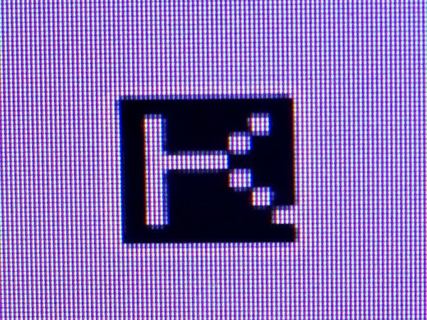
tynemouthsoftware_com-ZX80-K-Zoom

(The inverse K cursor as drawn by the 4K version of the ZX80. Image: Tynemouth Software.)

Here’s the post on the ZX80:

And here’s the one on the ZX81 and the “slow mode” (building on what we learned in the previous one):

3 Likes

It’s quite clever - for the time, brings a new dimension to “racing the beam” - Helped along with the on-board DRAM refresh circuitry.

It seemed Sinclair was always quite concerned with costs though - it was a cheap solution for the time - compare to the raft of TTL inside an Apple II or UK101 (Although I’m not sure what the Acorn Atom did in the same era, c1980).

-Gordon

I think, this also tells a story about the way they thought of these machines. This is not really about home computers as we know them, it’s more like if you start to think of the single-board computers of the time and about adding a keyboard instead of just some hex keys and a luxurious TV-screen instead of a basic 7-segment display – and still keeping this cheap. There are concessions to be made regarding performance, but this is surly worth it for the all the comfort and general accessibility gained… This is not about bringing the arcade to the home. That the Spectrum became Britain’s prevalent gaming machine is actually somewhat ironic, in this light.

1 Like

It used a CRT controller chip - the sort of big expensive chip which Sinclair would avoid.

I think the Spectrum was a clever evolution - the ZX80 was all commodity chips, the ZX81 got Sinclair started with ULAs (semi-custom chips) and quite possibly helped Ferranti’s ULA business in the process, and then the Spectrum used a bigger ULA and added low-resolution colour. I think all ULA designs could be, and were, prototyped with TTL. Acorn and Amstrad also used ULAs to good effect, and helpfully VTI got into the business too, doing (I think) a better job than Ferranti.

1 Like

These two articles (esp. the first one) were actual some kind of a revelation to me.
Firstly, I couldn’t imagine how the CPU could have kept up with CRT rendering, certainly, you couldn’t do it by instrcutions. So, how was it involved at all?
Secondly, I was always unsure about how to think of Sinclair computers in general. On the hand hand, they truly provided computing to the masses, much more than Commodore did, despite of its claim. And they did so quite uniquely. On the other hand, the designs fell short of what could have been done with just a bit more money, and they tied an entire industry down to this baseline, killing many more ambitious designs along the way. The perspective, I gained from this (see the comment above), puts me somewhat at ease with this.

Dr Matt Regan has been posting some videos on YouTube, where he explains AND builds a ZX80/ZX81 video siginal, following the original ZX schematics:

2 Likes

It’s worth comparing the Apple 1 with the Apple 2 to gain some insight into home computer design at the time. And also to look back at the TV Typewriter cookbook, for some perspective before the CPU era.

The Apple 1 was a TV teletype and a computer crammed onto the same mainboard, but otherwise still conforming to the usual standard.

The Apple 2 was a video graphics display with a CPU on the same bus as its RAM.

Consider that before the CPU era, the teletype was off-the-shelf hardware. So it made sense to design a computer that simply interfaced with that, rather than worry about the rather complex task of generating a video display and programming everything associated with that. The TV Typewriter Cookbook showed a way to make your own much more practical TV teletype, as an alternative to more expensive options.

But still, it was obvious that a less expensive home computer would be possible by adding a CPU to a video display generator rather than separating the tasks and putting some sort of serial interface between them.

So, that’s what the Apple 2, TRS-80 Model I, and PET 2001 did. They were all essentially video display generators with a CPU. The Apple 2 avoided snow by demanding fast RAM and alternating cycles to be used by CPU and video. But the other two initially just lived with snow.

Viewed in this context, the ZX-80 was just a really extreme examples of minimizing the component count, at the expense of not even trying to drive the display at the same time as CPU work. It was worse than just some snow, the entire display would lose its sync signals, resulting in nauseating display “rolling” whenever the CPU was done doing work and the computer spun up generating a display again.

It’s interesting that it worked at all, but it was never going to be a path to practical cheap home computers like a video chip. The VIC-20’s video chip included both video and sound, as well as some I/O. Its successor, TED, tried to cram in even more I/O functionality into a single chip - but it was evidently too much and it had problems with heat and such.

The basic thing, though, is that custom chips may cost more to initially develop, clever re-use of off-the-shelf chips just is never going to be able to do as much or as inexpensively (for a mass produced product, where the initial development cost is amortized).
1 Like

Yes, I think Commodore’s big advantage was really in owning MOS. Once you have your own fab, you’ve already paid a great proportion of the costs in making your own chips. So they could design chips which might or might not find their mass market. Anyone else would have to have a product in mind with very large projected volumes to make it reasonable to make custom chips. And then these custom chips are very cheap, so Commodore’s cost base will be lower than, say, Amstrad’s. (Apple are a special case because they never have competed on price, IMHO.)

The actual design and mask costs are still huge so their devices needed to find some kind of mass market volume or they would have lost money. It did mean they could get parts to their own specification and do interesting things that require fab magic (like mixed analogue/digital).

Commodore’s history on custom logic is not however that pretty when you look at it. The VIC was great for the VIC20, stretched for the C64 but never worked at the speeds the C128 could run (ditto the SID). The C128 ended up with a botched 80 column mode using a chip meant for some other dead unix project. Other mess ups lead to the incredibly slow floppy disk interface, a whole range of machines using a 6509 that never went anywhere, a super improved 6502 that was only ever used in an obscure amiga serial card and I imagine was a huge loss.

Off the shelf part vendors (eg Tandy) had the luxury of being able to pick winners other people had built, although even Tandy went bigtime into their own logic in the end for the GIME.

Thomson also made very good use of gate arrays. They avoided the M6845 (lots of other logic needed) and M6847 (relatively limited poor modes like the Dragon/COCO1-2) and had superb graphics as a result.

The sinclair video trick was not a new thing. Don Lancaster had published 6502 equivalents and more by then including TV video for the KIM-1 using that technique and I am sure the Sinclair folks would have known of that work. I’ve never seen the refresh trick anywhere else so I guess that was their cunning trick.

If you clock a Z180 correctly you an actually pull the trick almost totally in software. You take an NMI at the point you start the actual scan and the code is an out that flips hblank off , a bunch of ld x,y instructions where you pull the 4 usable bits off to encode pixels, and then an out that flips hblank back count and repeat. When you hit the bottom you flip the vblank on, run user code until the NMI timer which flips vblank back off, does the hblank etc - rinse repeat.

All the ld x,y instructions take 4 clocks, all encode 4 pixel data bits and all do nothing meaningful so providing you save/restore the registers top and bottom you don’t even need to muck around decoding nops or having end cases.

3 Likes

On the beam-racing front, it’s fairly straighforward on an ATmega at 16Mhz - you take an interrupt every 64µS then feed bytes into the SPI interface to send the signal out, one line every 64µS. You have spare CPU time at the end of each line when you flip hSync and more at the end of every frame when you flip vSync. I got 320x240 pixels (9KB) on an ATmega1280p in my tests but 40x24 text is possible in 1K of RAM by clocking the right data out of a fixed font area from Flash.

But when all you have is a 4Mhz Z80, that might not be a software option…

(And see e.g. the various ArduTV projects)

I did look at it in my 65C02 systems at one point - it’s a tight bit of code at 16Mhz and needs some sort of double-buffered SPI interface or other 8-bit parallel to serial shift-register that can do a back to back output stream with no gaps - but I’d be back to a fast/slow mode system as the time spent clocking out the video is quite large (about 70% of all CPU cycles in the ATmega) and I have bad memories of the screen flicker and fast/slow modes of the ZX80/81 …

But for cheapness (2 resistors) and some clever coding it’s a workable solution…

The Atari 2600 is probably the ultimate beam-racer though. (and it even did colour)

-Gordon

6502 can do it at low speed with only a tiny amount of extra hardware. See Don Lancaster’s “Cheap Video Cookbook” (and the sequel that chops it down even further)

2 Likes

This may be a naive question: As far as I can see, the only thing, the CPU can provide, is fetching the instruction code, which provides for about 24 characters per visible scan-line for a 6502 at conventional speeds. Notably, we already need some counter, some latch, and address decoding to access a character generator to produce pixels from character codes. Is it really worth it, as compared to adding a dedicated counter chain and leaving the CPU out of the loop, thus doubling the horizontal resolution (as an instructions is at least 2 cycles) and setting the CPU free, at the same time? Are the savings in hardware that significant?

The cookbook approach uses ORI #0 - which gives you one fetch per E clock which is rather better. It’s the same scheme used in things like the kimclone.

For old school through hole TTL parts it wasn’t a tiny amount of hardware (see for example the Jupiter Ace schematic that does this). Once you get to PALs and the like then it’s trivially not worth it. In the 6502/680x case there is actually less logic than the Z80 though because you can use the other half of the bus cycle and the only tricky bit is that your video RAM has to be fast enough to handle the speed, including have to chop the end of the write short before the end of the cycle and the video mux switching.

For the 6502/680x case the Motorola 6847 was pretty close to a single chip solution and I would imagine cheaper than a big pile of TTL logic but I don’t know what the Motorola prices were back then. Someone like MDSiegel might remember.

2 Likes

PCB board space was a big cost factor back then. A penny saved is a penny profit.
I think I read somewhere, a 50 cent part ends up $3.00 after all is said and done.

1 Like

I remember someone was crazy enough to produce video output using the 1MHz 6502 in a 1541 floppy drive. “Freespin” demo.

Easily enough resolution for a 2 column display.