Got some action… although its same excitement level when I tell my partner that I got a LED to blink
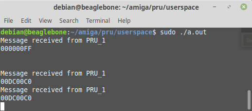
High and low address decode is working - I manage to intercept the memory bus reading the RTC address. Although nothing is there yet, its a good promise. 0x DCxxxx are all for a clock! … tons of wasted address spaces.
Congratulations! Partial address decoding is a good trick - it’s not wasteful, until you find you’re out of addresses. And then you can adjust your tactics.
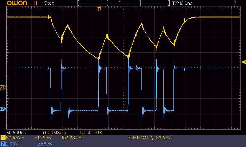
I have had to revise quite alot; the logic level converters are a source of pain and lots of noise, of which that noise was being sent down the power rails. A ton of decoupling has been added and next I going to try other level shifting methods. I have added to my blog of trials and tribulations.
Findings : Using a Zener clamp for level shifting resulted in a failure… or a success in learning. (I prefer the latter) - The generic 3v3 Zeners just cant do the speeds - also adding a ton of capacitance.
Yellow trace is output to Beaglebone… Cyan is 5V logic input…
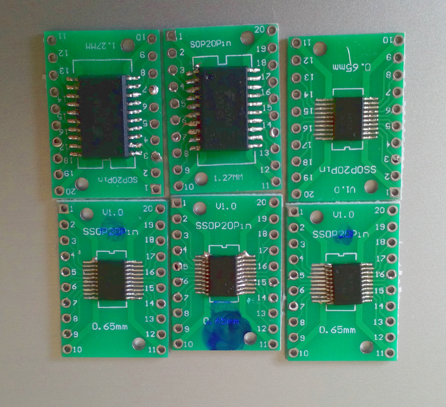
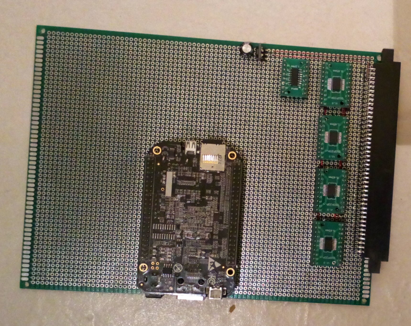
redesigning to use 74LVX conponents on the bus interface with standard 3.3V logic on the board only. I was hoping to use 5V until the final stages… but it doesn’t seem like a good idea anymore
74LVX244 for the address inputs and 74LVX245 for the bidirectional data bus.
The 4 muxed control/Data lines… One for RW/AE/LDS/UDS and the other 3 are Address lines 0…23
the 74xx137 is a 3-to-8-Decoder so I can use 4 lines and select one of the OE lines on the 74xx244 inputs.
Using the 74LVX244 as they have level shifters built in.