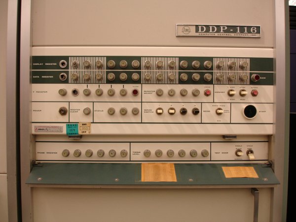
I do like a front panel! Here we have illuminated push-buttons, not toggle switches and lamps.
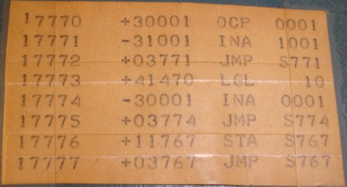
and I like it even more when there’s a short bootstrap routine printed out and taped on the front:
This is the DDP-116, from 1965, the first commercial 16-bit machine, selling nearly 200 units. Built to match the price of the PDP-5, using transistors for logic and core for memory, it was set back a bit by the PDP-8 coming out at a lower price.
The machine was invented because marketing wanted a machine to sell for $30k - that was the only constraint! (From this oral history of Gardner Hendrie)
More photos and info here
Main photos from Adrian Wise’s site which has much interesting detail on the series 16 machines:
They seem to have been consistent in their naming scheme, I did summer intern stints operating DPS-6:s in the 1980s.
Honeywell is a bit unknown in Europe, and have left the computer business long since (spun off to Honeywell-Bull, which I think has disappeared by now, too [edit: seems that Groupe Bull is still alive]), but they were similar to General Electric in doing a little bit of everything. I say were because they seem to have been subjected to a series of takeovers (including by GE!) and mergers and reorganizations, so much in that is it is hard to follow what they are actually doing these days. I guess the closest comparison in Europe would be something like Philips.
Hi, I stumbled upon a silly Pathe news reel on YouTube (here : Science Fiction | British Pathé ) and it features a DDP 416 with 2 ASR 33 (circa 2:44 min) ; although the purpose of the video is clearly goofy, we see clearly how the racks are setup inside the computer.
I also found a vintage leaflet online outlining the machine capabilities : http://www.ddp116.org/products/ddp416/ddp416.pdf
I have a punched paper tape from the USA secret testing facility in White Sands, NM. It states “Lunar Landing” on it. I was told to read or decode a Honeywell series 16 computer and flat bed scanner is needed. If anyone can help me please send an email to [email protected]
That’s highly interesting, @Edward_Staniszewski! I think almost any clear photo would help with decoding the tape. If you can supply a photo, perhaps someone here can try to decode.
How long is the tape - how many photos would you need to capture the whole thing?
This web page has some rather technical advice on using simple image processing to decode a punched card, which is a similar problem.
This is an interesting link. (I may want to adopt some of this to my own endeavors towards a general punched card scanner.)
While discerning punches is rather trivial, parsing a punched card is actually hard, since it involves locating the card on an image, figuring out the geometry, and discerning any punches from the background or card imprint. (E.g., it may be a highly exposed yellowish card on white background, or a card with black markings and logos on a dark background, etc. moreover, there may be no marks on the extreme rows and columns, so we have to either get the exact edges of the card or apply some heuristics to the location of any punches found in the overall geometry.)
Parsing paper tapes should be much easier, as there’s a reliable point of orientation in the central sprocket holes – and also just 5 rows of punches. Generally, parsing from a reliably constructed image is much easier than any general purpose solution. E.g., be sure to align any paper tapes perfectly to the top edge of the scan bed and to scan them using the same settings. This way, your life will be much easier, since you may start at some solid assumptions, regarding where the holes/punches may be located and at what distance they may be separated. I’d suggest by locating the sprocket holes first, as everything else may be inferred from their location and the distance between sprocket holes. (If you apply some discipline to your scanning, these should be about the same on each scan and only the horizontal start position/offset is to be determined.) Also, colors, contrast and background should be about the same on each image, so you may omit the tedious part of figuring this out and start with some hard coded averages.
Be sure to include some visual feedback, regarding the scanned image and the punches recognized by the application.