On the Swedish Electronic magazine (see image) I found this line code.

It’s about writing digital bits to magnetic tape.
Can someone explain e)?
How is it called? How does it work? What computers used it?
On the Swedish Electronic magazine (see image) I found this line code.
It’s about writing digital bits to magnetic tape.
Can someone explain e)?
How is it called? How does it work? What computers used it?
The description says that it uses a sine wave where no phase change gives a 0 and a phase change gives a 1. So where you would expect the signal to cross the zero line and it instead changes phase to “bounce” back, you get a 1.
I’d interpret this as a variation of RB (return to bias, fig. 2-b) using a sine wave (and it’s inverted form for inverted peaks). It seems that the decisive element is the polarity after the return to bias. (Is the signal diverting to the positive or negative side after the return to bias?) So, when switching bit values, the signal uses a half-wave to cross the bias, rather than “bouncing” back from it by alternating basic and inverted quarter-wave forms. So, rather than using polarities, we’re switching phases.
What seems interesting about this is that using a biased cutoff value for reading this would give you something similar the NRZ (no return to zero) as in fig. 2-d, but it also includes a timing reference.
Mind that this only true, if the signal for two consecutive zeros would be two quarter wave forms on the positive side, for which there is no example.
The description actually indicates otherwise: It’s just about phase switching. A phase switch is 1, no phase switch (half-wave) is 0.
The description reads (Google translate):
A sinusoidal voltage can also be used, as can be seen from Fig. 2 e. Here “1” is indicated by phase change and “0” by no phase change.
Of these registration methods, only RZ [return to zero] does not require a clock signal; this is because each bit is represented by a pulse. The clock signal is generated by a very accurate pulse oscillator and is used to determine the recording rate.
No idea, what this is called or were this has been used.
Edit: Ah, I see, while I was taking my time, @davidb has already figured it out.
Sorry about that! I just quickly skimmed the description and got the gist of it. I saw that you were replying and was expecting you to fill in the finer points. ![]()
So it’s BPSK as described at wikipedia. No nice picture…
it handles the highest noise level or distortion before the demodulator reaches an incorrect decision. That makes it the most robust of all the PSKs.
but
In the presence of an arbitrary phase-shift introduced by the communications channel, the demodulator (see, e.g. Costas loop) is unable to tell which constellation point is which.
And I was looking up old tape manuals to come up with a reference for this… to no avail.
PSK (phase-shift-keying) seems to be much more used nowadays (WLAN, mobile telephony, etc) than it was then. “Sinusoidal phase modulation” may be another keyword.
And by the way, my finer points were totally wrong… ![]()
Thanks for your efforts and translation.
Unless if it isn’t a theory or experimental (and it’s not described as such) it must have been in use and there must be hardware, documentation and patents.
Maybe it’s Frequency-shift keying with a carrier signal
or maybe just analog.
Obviously it’s very rare and maybe used for special purposes like medical or military. In later magazines there was much medical hardware shown.
diagram ‘e’ is an interesting hybrid of half-wave rectification plus full-wave. I don’t think I’ve seen that one before.
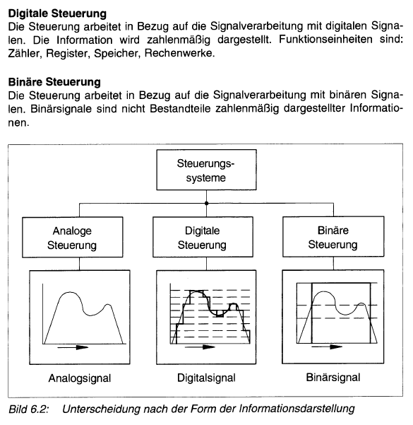
By coincidence I found in a book about FESTO PLC, called Pneumatik Grundstufe, this similar diagram (p. 211), two lines 0/1 but not digital
Next to analog and digital control, there’s a “binary control”. I always thought digital and binary would be the same. One page earlier the DIN standard is mentioned, DIN 19237.
I searched for that. One example is a staircase timer, where the lights are turned off after a specific period. And no need for arithmetic operations.
Maybe it’s similar here. So a special computer, maybe medical.