Right, so I got curious about this and hauled out the FM-7 to do some experimentation. The theory I now have for the FM-7 display is:
- The system always generates 640×200 video.
- The standard glyphs are stored as a 6×7 dot matrix.
- The sub-CPU, when asked to print a character at a certain spot on the screen, renders it as-is in
WIDTH 80 (80-column) mode and double-width in WIDTH 40 mode.
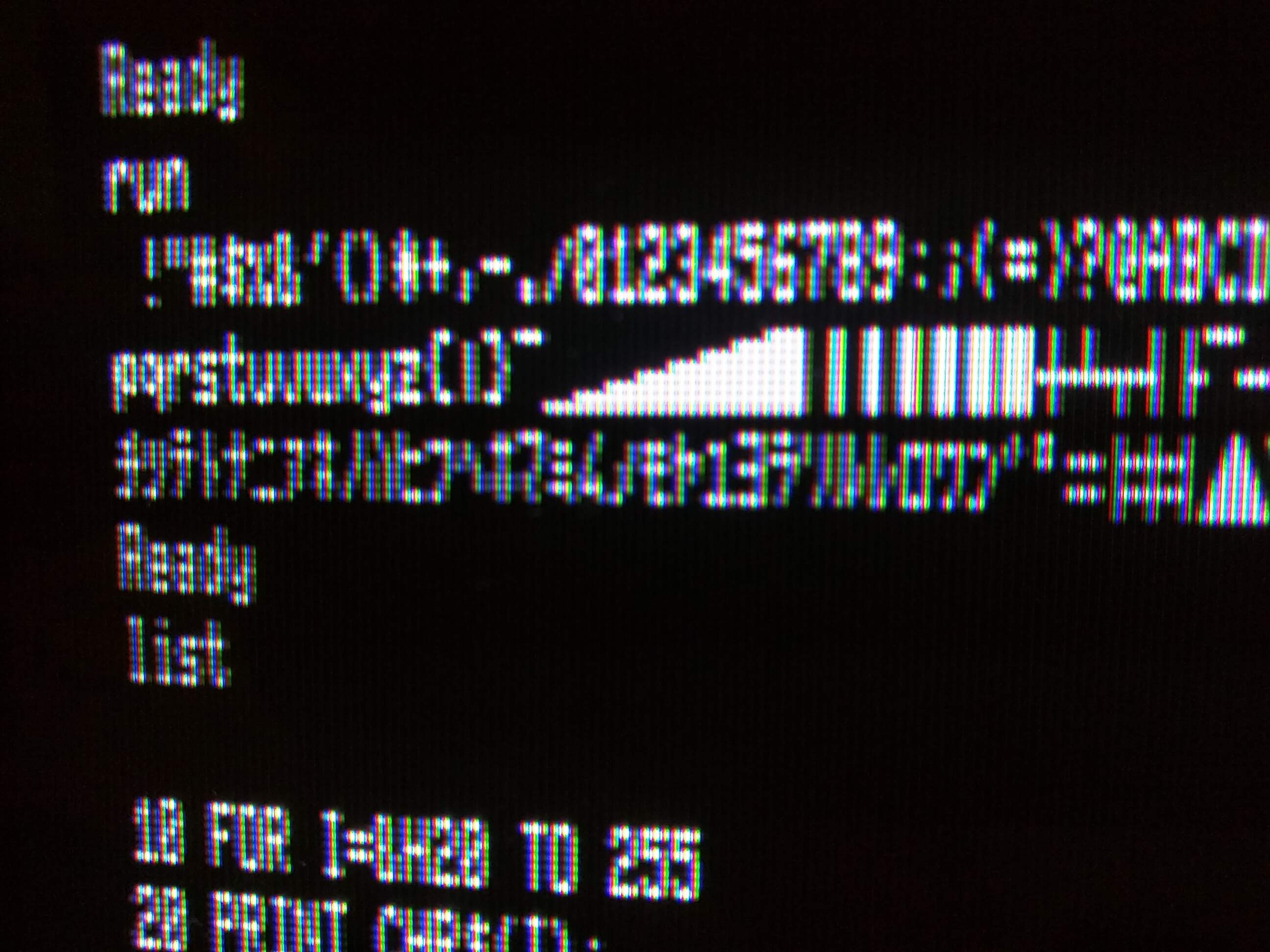
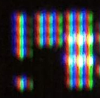
I worked this out by using the SYMBOL (x,y),"c",hscale,vscale command in FM-BASIC, which plots character c at (x,y) on the screen (x ranging from 0-639 and y ranging from 0-199) scaling it horizontally by hscale and vertically by vscale. Scale factors of 1,1; 2,1; and 8,4 look like this:
(This image was photographed from on my 450-line PVM-9045Q, and under different conditions from the photos in my previous post, so don’t use that to compare resolution, just use it confirm the character dot matrix.)
The ヨヨヨラリルレロロ line at the top was printed using the standard (40-column) text output so you can see the standard inter-character spacing, which I can’t do with SYMBOL since that plots only one character at a time at arbitrary co-ordinates. It looks like those add one column of pixels for spacing, giving 7 pixel-wide characters, but they should be 8 pixels wide for 80 chars on a 640 pixel line. I have no idea where the extra pixel went.
Anyway, going back to my previous post’s image:
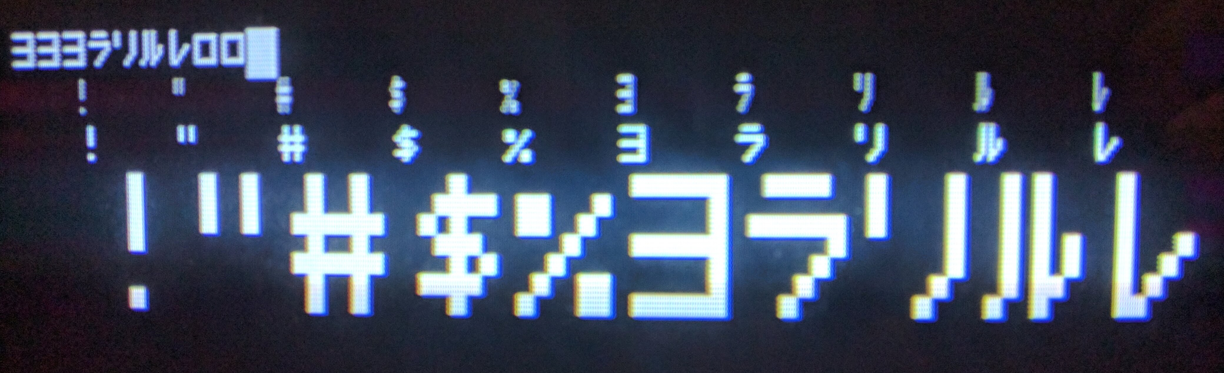
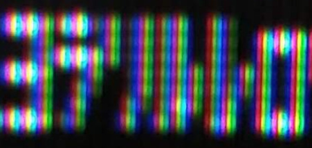
I can’t find the “I” you’re referring to, but if we have a look at the exclamation point, which is one pixel wide, and the double quote and octothorp to the right of it (the !"# character sequence), we see pretty clearly that each character is getting about three lines of horizontal resolution on the 250-line PVM-9042Q, and can see the adjacent red, green and blue phosphors in each line:
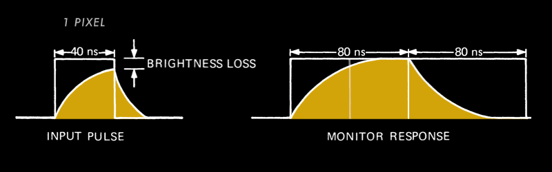
I think you’re right that there’s a “reaction time” thing going on here, but I don’t think it’s anything to do with the phosphor: it’s simply that the analog signal, continuously varying across the scan line, is (partially) “digitized” by the aperture grille, i.e. you see only the sections of signal where it’s not been blocked by the grille. (There are actually three signals being displayed, for R, G and B, but since the composite output is monochrome, R, G and B will all be at the same level.) So if you have several adjacent horizontal pixels lit up that fully cross the R, G and B phosphor columns in front of the grille, you’ll get a nice bright white, as you see for the horizontal lines in the octothorpe. But when only one pixel is being lit by the computer, that’s not enough to cover the full width of an aperture grille column, so you’ll see that section only partially lit up because the signal is “on” for part of it and “off” for part of it. (Actually, it is truly analogue; there will be a rise and fall time there, but I imagine that the column will simply average out the total energy value of the signal as it varies over that column.) Thus the double-quote, pattern .█..█. , ends up more or less evenly lighting all three columns.
This also seems clear in the sequence of “ヨラリルレロ” where there are eighteen vertical slices of the aperture grille across the six characters, and though I suspect the beam can resolve this, the aperture grille cannot:
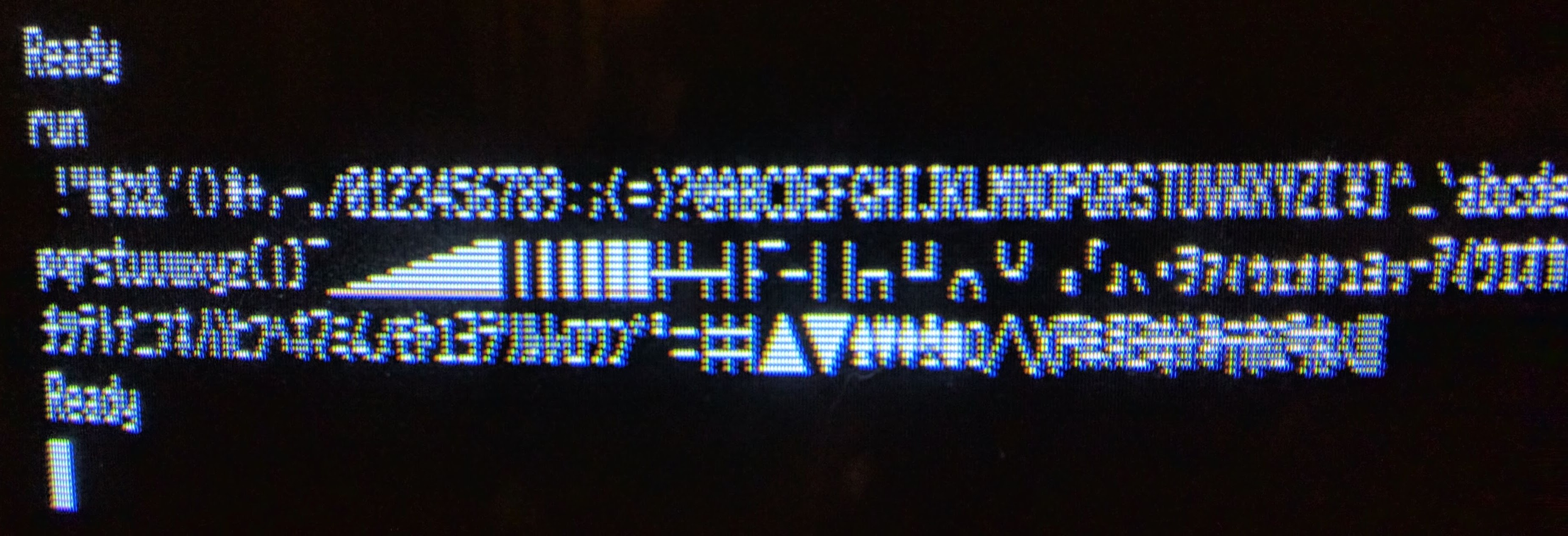
Here’s the 80-column character sequence on the 450-line PVM-9045Q.
I’m not sure how reliably these can be compared, because my camera doesn’t have manual controls for me to get consistent images, but if we extract the same “ヨラリルレロ” sample to show it here full size:
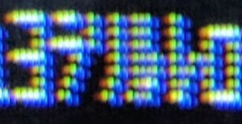
I count something like 35 vertical lines there, which isn’t too far off from the calculating 18*450/250 = 32.4 lines. The individual coloured columns don’t come out in that image, or any others I’ve taken, though. I don’t know if that’s an issue with the photography or if something’s different about the monitor.
Now that I’ve done all this, I’m not sure if I’ve become less confused or more confused about this. But at least I know to check for lines of horizontal resolution on colour monitors and that 450 lines is kind of a bare minimum for 80-colum work. :-)