I recently downloaded the z80 source code for a Spacewar game. It was written in 1977 for a z80 system with a Tetronix graphics terminal, and it was updated in 2008 to work with a terminal emulator that supports dectek graphics mode. However I tried running the code and I get nothing displayed in the dectek graphics window. I know nothing about Tektronix graphics and I have not been able to find much technical info about it. I’m hoping someone here can point me at dectek documentation or code examples that could help debug why this game is not working.
I don’t know about dectek graphics, specifically, but the Tektronix graphics terminals speak a simple-but-strange base32 coordinate system that is mapped to printing ASCII characters. You can find the details here:
http://www.bitsavers.org/pdf/tektronix/401x/070-1225-00_4010um_Jul81.pdf
Or, for a slightly later version that has some extra features that games would love, here:
http://www.bitsavers.org/pdf/tektronix/401x/070-1647-00_4014_UsersMan_Nov79.pdf
I hope to get a video out about these terminals very soon.
2 Likes
You might also find this project valuable:
It is a high quality software implementation of the 4014 that preserves a lot of its unique features, such as a bright “drawing” trace and a dimmer “drawn” trace.
3 Likes
Hi Ethan,
There are a number of .plt file in the above tek4010 emulator project. Do these .plt files just contain graphics commands of is there other meta-data embedded in the file and if so what is the format?
Thanks,
Scott
The standard Unix/Linux “xterm” terminal emulator has a built-in Tektronix 4014 emulator. Start it with the “-t” option.
1 Like
I would expect a *.plt file just to be a sequence of characters to be written: if on Unix, they’d be suitable to ‘cat’ to the terminal.
As @EdS suggests, they can just be catted directly to a compatible terminal. They are a raw command stream for the terminal.
The terminal has very few “graphics commands”, depending on the version of the terminal targeted. If it’s the basic 4010, there are pretty much only two: ASCII GS (\035), which enters the terminal into graphics mode, and ASCII US (\037), which returns it to text mode. You can also query the location of a pointer crosshair, but I don’t remember exactly how. Between a GS and US command, you send one-to-four-byte ASCII character strings that specify a coordinate on a 1024x1024 (10-bit square) grid. The manual specifies how they are encoded, it uses a base32 encoding where the range of selected characters varies depending on whether you are sending the high byte of the X coordinate, the high byte of the Y coordinate, or a low byte. The first coordinate sent after GS moves the electron gun to that location without drawing anything; every subsequent coordinate until a US draws a vector from the previous location to the new. US returns the terminal to text mode, with the cursor immediate above and to the right (if I remember correctly) of the last-specified coordinate.
Vectors or text cannot be erased without erasing the entire screen. This is done with ASCII ESC (\033). The canonical reset sequence is \033\014, which is ESC FF, or ESC Ctrl-L. This blanks the screen and returns the cursor to the “home” position at the top left, which is something like (0, 769).
(Oh, and that’s another thing to know; 0,0 is the bottom left corner of the display, and while the coordinate grid is 10 bits square, only 1024 x 780 is actually visible on-screen.)
For more detail than that, and the base32 encoding, you’re really going to want to look at the programming section of one of those manuals. As I recall, the 4012 and 4014 manuals are somewhat easier to read than the 4010 manual, but the 4014 adds the complication of several commands that are not supported by earlier terminals.
1 Like
I wrote a (z80) test program to send .plt file data to the 4010 emulator and that works fine.
Then I wrote a second test program to convert x,y Cartesian coordinate data to Tek data format.
I based this on Fig. 3-7 of the Tek 4010 User’s Guide
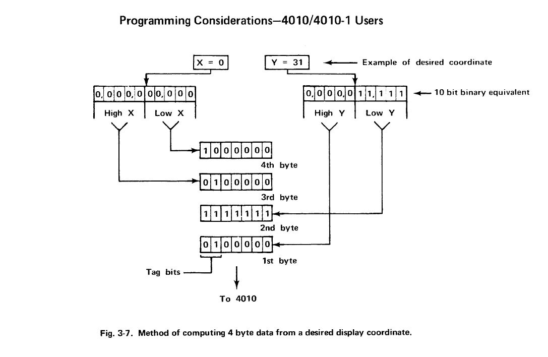
For example: given the input data of X=0c8h, Y=064h
the program calculates the Tek data as: Yhi=23, Ylo=64, Xhi=26, Xlo=48
Which (I think) is correct according to Fig 3-7, but I am not getting the expected result.
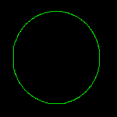
Here is what I get when I try to plot the circumference of a circle.
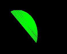
Any thoughts as to what might be wrong?
First, I know virtually nothing about Tec terminals, so I won’t be of help with any specifics. But, judging from your screenshot, it looks much like you’re jumping between positive and negatives coordinate values (and somehow ignoring the sign), which results in the diagonal lines.
Hi Norbert,
Yes somehow I am flipping from one side of the circle to the other rather than following the circumference path. All x,y locations on the Tek 40xx screen are positive. 0,0 is in the lower left and 767,1023 is in the upper right. The conversion from x,y Cartesian coordinate data to Tek data format is just shifting bits around and adding tag bits as is shown in Fig. 3-7.
BTW (if anyone is interested) Here s the z80 code I used to do the conversion:
;-------------------------------------------------------
; tekx and teky
;
; Convert a 10-bit quantity in hl to tektronix 40xx
; high/low data bytes and send them to the uart
; This conversion algorithm is described in the Tek4010
; User's Manual (Rev B July 1975) on page 3-8
; Note: register c is overwritten by these routines
;-------------------------------------------------------

tekx:      ld   c,40h     ; x low data tag (10)
           jr   tekxy

teky:      ld   c,60h     ; y low data tag (11)

tekxy:     push hl
           push bc
           ld   a,l
           and  0e0h      ; mask off low data
           ld   b,h
           or   b
           rlca
           rlca
           rlca
           or   20h       ; high data tag (01)
           call putc      ; send high data
           ld   a,l
           and  01fh
           or   c         ; low data tag
           call putc      ; send low data
           pop  bc
           pop  hl
           ret
I concur with all of your calculations in this post, and I think @NoLand is right that the problem must be in what you are trying to plot.
For those following along at home:
Tektronix terminals use a four-byte coordinate representation, in which some or all of the bytes may be elided of the current coordinate is “near” the previous coordinate. It’s not clear to me that this was actually a design decision, as it is more expensive to encode Y changes than X changes, which seems arbitrary, but rather I believe it is because it made decoding coordinates and triggering vector output simpler in discrete logic.
The chart that @scd posted is the coordinate conversion chart. The total plotting grid for the terminal is a 1024x1024 matrix, which means it is 10 bits high by 10 bits wide. The encoding for this is somewhat strange, however. The top 5 bits of both the X and Y coordinate are encoded using the same set computation to produce Xhi and Yhi; that value is 32 + the integer value of those top 5 bits. This is what the table above says. The low order five bits are added to different values (64 for X and 96 for Y) to form Xlo and Ylo.
The coordinates are transmitted to the terminal “big endian”, with the high 5 bits (after encoding) sent before the low 5 bits (after encoding). Y is sent before X. Because Xlo and Ylo occupy a different range, a vector to a location that does not differ in Xhi and Yhi can be transmitted by sending only Ylo followed by Xlo, and the terminal will leave the high bits unchanged. In the case that only the X coordinate is changing, and it is in the same 5-bit range on the display, a lone Xlo byte can be sent.
The X coordinate in the example case given by @scd is decimal 200, which is 32 * 6 + 8. This means that Xhi is 38 (26h), or &, the same as you computed. Xlo is 72 (48h), H, the same as you computed. The Y coordinate is decimal 100, which is 32 * 3 + 4; this makes Yhi 35 (23h), #, and Ylo 100 (64h), d. Thus to plot to the coordinate (200, 100), you would send to the terminal the ASCII sequence &H#d.
Interestingly, the 4010 cannot produce any Ylo except for 0 (`) or 31 (ASCII DEL) due to the limitation of being an ASCII uppercase-only keyboard.
Hi Ethan,
I found a bug and as you suspected it is not in the the conversion routine. The conversion routine was indeed being fed the wrong data. I should have a fix soon.
Thanks !!
Scott
The test program works fine now…
Now on to debugging Spacewar …
4 Likes
I’m curious about any specifics of this version. Please make sure to post any updates.
Hi Norbert,
This version of Spacewar was originally written for the Altair 8800. It is simplified as compared to the original PDP-1 version as it doesn’t have a central star or gravity or a star field.
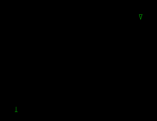
The changes I made to the original 8080 code are: a) convert to z80 opcodes b) change the I/O routines, and c) change the 10 ms timer routine. Currently the initial state looks OK, but quickly breaks once I try to move the ships. I haven’t debugged why yet. Here is a screen shot of the initial state.
Regards,
Scott
Nice to see it’s still the Wedge and the Needle, and not Star Treck ships.
In case you eventually wanted to implement the gravitational star (AKA, heavy star), have a look at Spacewar_3_1.js (source view)
This is my attempt to convert the original PDP-1 code to a more platform neutral format, here JS. (The original code isn’t only in assembler, but also uses DEC Type 30 screen coordinates as fixed point math for coordinates, 10 signed significant integer bits and 8 fractionial ones.) While gravity requires multiplication and integer square roots, gravity factors could be easily precalculated for a quadrant and stored in a lookup table. Mind that the original Spacewar coordinate system has the origin at its center.
I have uploaded a working version of z80 SpaceWar to GitHub.
There are many enhancements that could be made to it (e.g. central star gravity) but I think I’m done for now ![]()
3 Likes
Great - splendid collection of demo programs (pi, life, lunar, basic…) I do hope you release the HDL source too, in due course.