I’m currently stuck with my Festo PLC programming device. I found a later Festo software which is very interesting, but is too late to be helpful for my device. So I searched for other (early) PLCs.
I recently bought a 1990s student’s book with comparison and problems for 4 different PLCs (AEG Logistat, Klöckner-Moeller PS3, Mitsubishi Melsec F1 and Siemens S5). The instruction lists of AEG and Siemens are very similar and the later Festo is also similar but still has it’s unique wenn… dann (if then) clause, now abbreviated to w and d.
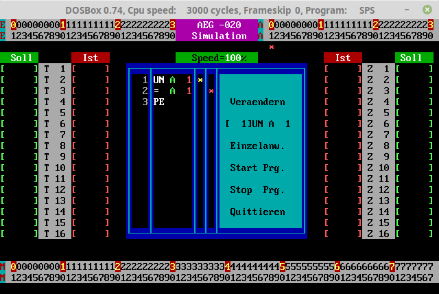
Searching for the AEG Logistat A020 (later renamed to Modicon) I found some interesting facts and even a simulator. The programming device for that PLC is called AEG P020, but in fact is a TI CC-40 with LCD 1x31. (Needs a BASIC software).
It was also programmed via software Dolog AK under MSDOS 6.
Here I found some photos showing hard and software. On this screen you can see both a ladder diagram and the instruction list (German: AWL, Anweisungsliste). U means and (und), E is input (Eingang), A is output (Ausgang). E1 is an input for a counter (Z=Zähler).
There is a DOS simulator on github also showing photos of the outside and inside of the PLC. But that is not emulating Dolog. I think you need a PLC and a terminal software. So it’s probably not much useful without one.
In the late 80’s I attended a week-long course given at TI in Bedford to learn all about their PLCs and ladder, etc. I have a nice certificate somewhere… (The intention was that the people I was working for were going to develop their own so we needed to know how they worked, but maybe more of that another day)
I did then use that knowledge to do some work on a TI PLC but I never did like ladder logic - I always felt it could be done better in software on a microcontroller (which for me was the 6502 at that time). However it’s easily understood by electrical and mechanical engineers and ladder still soldiers on today…
Oh, I did a mistake. It’s not ladder logic on the left but looking similar.
I think it’s just called wiring diagram (Stromlaufplan in German). Another one is Function block diagram (in German previously FUP).
Real Ladder logic looking like this. There are slight differences between manufacturers and also depending on printer and screen. But I think this is rarely used today.
Ladder typically goes from left to right in blocks stacked vertically - hence the term Ladder, each block being executed effectively concurrently with inputs on the left and outputs on the right - that first picture reminded me of it, although it looked to me like it was going sideways rather than up/down.
Programmers then were expensive (still are) - dedicated terminals with a means to load/save the systems and fancy font/graphics to represent the block. These days I think it’s all done on a WinPC, but the cable still costs many many £…
So Ladder is still in-use today, still expensive, but you get what you pay for - that £10K+ PLC comes with industrial grade digital and analog IO and manufacturers support vs. the home-brew Arduino-grade thing with virtually no support, but costs a tiny fraction…
I found this out a few years back when I did thought PLCs had gone the way of the dinosaur to be very much surprised - I was doing a control project for a couple of friends starting up a micro brewery - lots of existing solutions using PLCs costing £30K upwards, but they just couldn’t afford it - so I made up some “working prototypes” using Arduinos and a home designed IO board for process control things like washing machines, heater and pump controls… (And 5 years later those “working prototypes” are very much still in-use!)